
AERO-300 · Lesson 12 of 12 · 24 min
High-lift devices
A wing sized for efficient cruise has too little area to land slowly. The Tern's clean wing could carry the aircraft at 380 km/h with a lift coefficient of 0.45, but to land on a short gravel strip it needs a lift coefficient more than five times higher. High-lift devices bridge that gap. In this final lesson Arjun works through how flaps and slats raise the maximum lift, sizes the Block 2 flap system against the airline's requirement, and joins the design review in which Tomasz's group presents the whole Block 2 wing.
Why high lift matters
The stall speed in a given configuration depends on the wing loading and the maximum lift coefficient. The approach speed is typically 1.3 times the stall speed in the landing configuration, and the landing distance grows roughly with the square of the approach speed, since the kinetic energy to be absorbed does. A higher maximum lift therefore shortens landing and take-off distances, lowers approach speeds, which helps safety, and lets the designer use a smaller wing with less drag and weight in cruise.
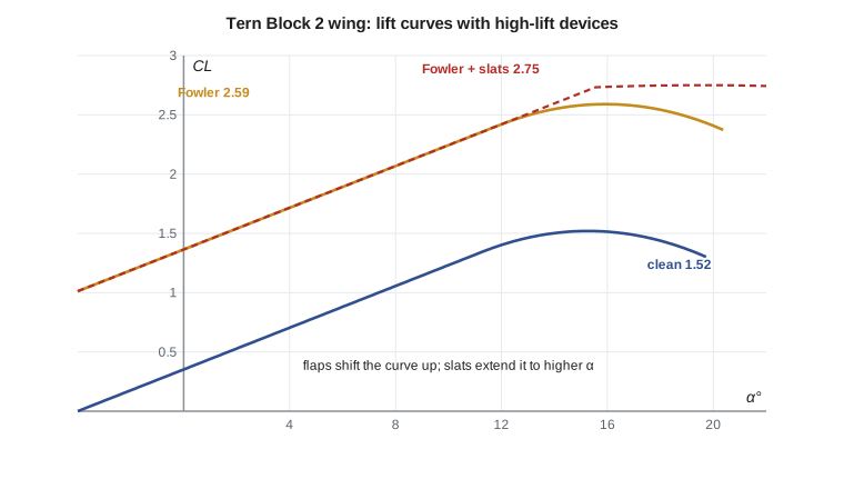
Lesson 11 estimated the Block 2 clean wing's maximum lift coefficient at 1.52. The original Tern reached about 2.6 with flaps at the landing setting, and the airline's guarantee for gravel-strip operations in northern Manitoba is built on that figure. The Block 2 wing must do at least as well, with flaps that are simpler to maintain than the original's.
Trailing-edge flaps
A trailing-edge flap is a hinged or sliding rear portion of the wing. Deflecting it downward increases the camber, which, as thin airfoil theory showed in Lesson 6, shifts the lift curve to the left: the zero-lift angle becomes more negative and the lift at a given angle of attack rises. The maximum lift also rises, though the stall angle usually falls a little. The main types differ in how well they keep the flow attached over the deflected flap.
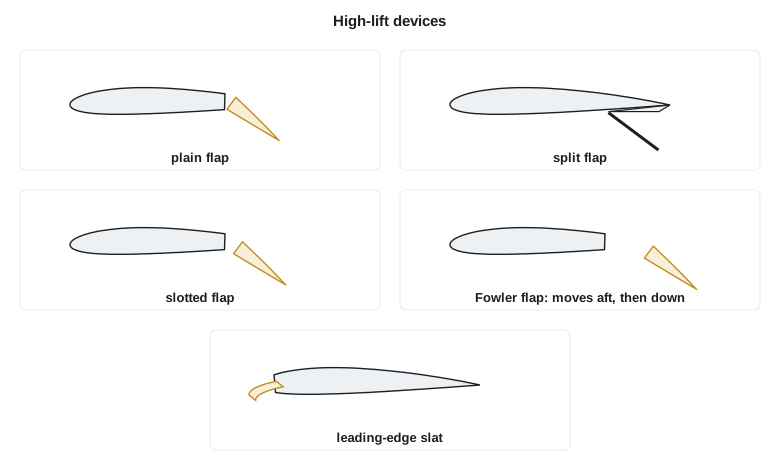
A plain flap is simply the rear of the section hinged downward. It is light and simple, but at large deflections the flow separates from its upper surface, so its useful deflection is limited to about 20 degrees and its gain in maximum lift is modest. A split flap hinges only a plate from the lower surface. It produces about the same increase in lift with a large increase in drag, which is useful on approach when the pilot wants to descend steeply; it was common on aircraft of the 1930s and 1940s.
A slotted flap leaves a carefully shaped gap between the main wing and the flap. Air from the high-pressure lower surface flows through the slot and emerges over the flap's upper surface as a fresh, high-speed layer. The flap's boundary layer starts anew, and the main wing's trailing edge sits in the induced flow of the flap, which reduces the pressure recovery the main wing's boundary layer must achieve. The two effects let the flap deflect to 35 or 40 degrees with attached flow and give a much larger gain. A double-slotted flap adds a second element and slot and works at still larger deflections. A Fowler flap moves aft on tracks before it deflects, so it also increases the wing area and chord. Fowler flaps are the standard on airliners and many commuter aircraft because they give the largest gain per unit of drag.
Leading-edge devices
Trailing-edge flaps raise the lift at a given angle, but they do little to raise the stall angle, which is set by the suction peak at the leading edge. Leading-edge devices attack that problem. A slat is a small airfoil-shaped element that moves forward and down ahead of the main wing, leaving a slot. The slat itself carries part of the suction peak, and its wake and induced flow reduce the peak on the main wing behind it, so the main wing can reach a higher angle of attack before separating. A Krueger flap, hinged from the lower surface of the leading edge, does a similar job on thin wings. Leading-edge devices extend the lift curve to higher angles more than they shift it upward, which is why aircraft with slats land in a more nose-up attitude.
Estimating the gain
Accurate prediction of high-lift performance needs viscous computations and wind tunnel tests, because the flow through slots and over multiple elements is complex. For early sizing, engineers use handbook methods based on large collections of test data. A common approach takes the increase in section maximum lift for each device type and converts it to a wing increment by multiplying by the fraction of the wing area served by the device and by the cosine of the hinge-line sweep, with a factor of about 0.9 for three-dimensional effects.
| Device | Typical Δc_l,max (section) |
|---|---|
| Plain flap | about 0.9 |
| Split flap | about 0.9 |
| Single-slotted flap | about 1.3 |
| Double-slotted flap | about 1.6 |
| Fowler flap | about 1.3 to 1.6 times c′/c |
| Leading-edge slat | about 0.4 times c′/c |
| Leading-edge droop or Krueger flap | about 0.3 |
# High-lift sizing for the Tern Block 2 wing: flap increments, landing CLmax and stall speeds
import math
m, g, S = 6500, 9.81, 28.0
W = m * g
clean_CLmax = 1.52                          # lifting-line estimate with 2.5 deg washout (Lesson 11)
def stall(CL, rho=1.225): return math.sqrt(2 * W / (rho * S * CL))
# Section increments in maximum lift at landing deflection (typical handbook values)
flaps = {'plain flap': 0.9, 'split flap': 0.9, 'single-slotted flap': 1.3,
         'double-slotted flap': 1.6, 'double-slotted Fowler, chord +20%': 1.6 * 1.20}
Sf = 0.62                                   # flapped wing area / reference area
hinge = math.radians(2.0)                   # sweep of the flap hinge line
for name, dcl in flaps.items():
    dCL = 0.9 * dcl * Sf * math.cos(hinge)
    CL = clean_CLmax + dCL
    print(f"{name:34s} dCLmax = {dCL:.2f}  CLmax = {CL:.2f}  stall {stall(CL) * 3.6:5.1f} km/h ({stall(CL) * 1.94384:4.1f} kt)")
slat = 0.9 * 0.4 * 0.45                    # outboard slats on 45 percent of the area, section increment 0.4
best = clean_CLmax + 0.9 * 1.6 * 1.20 * Sf * math.cos(hinge)
print(f"Fowler plus outboard slats: CLmax = {best + slat:.2f}, stall {stall(best + slat) * 3.6:.1f} km/h")
for Vs_kt in (75, 73, 71):
    Vs = Vs_kt / 1.94384
    print(f"a stall speed of {Vs_kt} kt needs landing CLmax = {2 * W / (1.225 * S * Vs ** 2):.2f}")
for CL in (2.41, 2.59, 2.75):
    Vref = 1.3 * stall(CL)
    print(f"CLmax {CL:.2f}: Vref = {Vref * 3.6:5.1f} km/h, energy to absorb {0.5 * m * Vref ** 2 / 1e6:.2f} MJ, "
f"landing roll relative to CLmax 2.59: {(2.59 / CL):.2f}")plain flap dCLmax = 0.50 CLmax = 2.02 stall 154.4 km/h (83.4 kt) split flap dCLmax = 0.50 CLmax = 2.02 stall 154.4 km/h (83.4 kt) single-slotted flap dCLmax = 0.72 CLmax = 2.24 stall 146.5 km/h (79.1 kt) double-slotted flap dCLmax = 0.89 CLmax = 2.41 stall 141.3 km/h (76.3 kt) double-slotted Fowler, chord +20% dCLmax = 1.07 CLmax = 2.59 stall 136.4 km/h (73.6 kt) Fowler plus outboard slats: CLmax = 2.75, stall 132.3 km/h a stall speed of 75 kt needs landing CLmax = 2.50 a stall speed of 73 kt needs landing CLmax = 2.64 a stall speed of 71 kt needs landing CLmax = 2.79 CLmax 2.41: Vref = 183.8 km/h, energy to absorb 8.47 MJ, landing roll relative to CLmax 2.59: 1.07 CLmax 2.59: Vref = 177.3 km/h, energy to absorb 7.88 MJ, landing roll relative to CLmax 2.59: 1.00 CLmax 2.75: Vref = 172.1 km/h, energy to absorb 7.43 MJ, landing roll relative to CLmax 2.59: 0.94
Sizing the Block 2 flaps
The Block 2 flaps can span 62 percent of the wing area, from the fuselage side to the inboard end of the ailerons. With a plain or split flap the program gives a landing maximum lift coefficient of only about 2.0, and a stall speed of about 154 km/h. A single-slotted flap reaches 2.24 and a double-slotted flap 2.41. Only the double-slotted Fowler flap, extending the chord by 20 percent, reaches 2.59, matching the original Tern's 2.6 and giving a landing stall speed of about 136 km/h. Adding outboard slats would raise the maximum to about 2.75 and cut the stall speed to 132 km/h.
The lower part of the output connects these numbers to operations. A stall speed of 73 kt would need a maximum lift coefficient of 2.64, beyond what the Fowler flap alone gives. Every improvement in maximum lift lowers the reference speed and the energy the brakes must absorb: going from 2.41 to 2.59 cuts the landing roll by about 7 percent, and adding slats would save about another 6 percent.
The Block 2 design review
Tomasz presented the Block 2 wing to Élise Fournier, the chief engineer, and the programme team. The summary drew together every lesson of the course. The wing keeps the Tern's 17 m span and 28 m² area, with a taper ratio of 0.45 and 2.5 degrees of linear washout, giving a span efficiency of about 0.97 and a section lift peak near the root. It uses NACA 4415 sections at the root and 4412 at the tip, both of which stall gently from the trailing edge at the Tern's Reynolds numbers, with predicted zero-lift angle of minus 4.15 degrees and quarter-chord moment of about minus 0.1. Its clean maximum lift coefficient is estimated at 1.52. Double-slotted Fowler flaps give a landing maximum of about 2.59. Stall strips at the root and vortex generators ahead of the ailerons tune the stall, and heated leading edges protect against ice.
Two questions were debated. First, should the wing have slats? They would add 0.16 to the maximum lift and shorten the landing roll, but they need tracks, actuators and their own ice protection, and slat leading edges are damaged by gravel spray. The team recommended no slats: the Fowler flaps meet the guarantee, and the margin can come from reducing the aircraft's landing weight on the very shortest strips. Second, should the span grow by a metre to cut climb induced drag by about 11 percent? Marcus Webb's structures group estimated the extra root bending moment would add about 60 kg to the wing, and the airline's hangars in northern Manitoba have tight door widths. The review chose small winglets instead, worth about 4 percent of climb induced drag for much less structural penalty.
Élise approved the wing for detailed design, with two conditions. The wind tunnel test in the 9 m tunnel must confirm the maximum lift and stall pattern before the flap tracks are ordered, and flight test must demonstrate the stall characteristics with the ice-protection system both working and failed. Arjun's last task of the work term was to write the test plan for the tunnel entry: the configurations, the angles of attack, the tufts and oil flow needed to see where separation starts, and the Reynolds number corrections the team will apply. AERO-310 continues with compressible flow, where the Tern's cruise Mach number of 0.32 begins to matter and where faster aircraft meet shock waves.
Worked problem
Flap span needed for a target stall speed
Suppose the airline asks for a landing stall speed of 73 kt (37.6 m/s) at 6500 kg at sea level, with double-slotted Fowler flaps (section increment 1.92) and no slats. What fraction of the wing area must the flaps serve, keeping the clean \(C_{L,max} = 1.52\) and a hinge sweep of 2 degrees?
Show solution
- Required: \(C_{L,max} = 2\times 63\,765/(1.225\times 28\times 37.6^2) = 2.63\).
- Increment needed: \(2.63 - 1.52 = 1.11\).
- \(S_f/S = 1.11/(0.9\times 1.92\times\cos 2°) = 0.643\).
Answer: The flaps would need to serve about 64 percent of the wing area instead of 62 percent. That means shortening the ailerons slightly or adding a small amount of chord, a trade the team could make if the airline insisted, but it would reduce roll control power.
Worked problem
Effect of high lift on the landing roll
With flaps giving \(C_{L,max} = 2.59\), the Tern's landing ground roll on dry gravel is 1042 m. Estimate the roll with \(C_{L,max} = 2.41\) and with 2.75, assuming the same braking.
Show solution
- Ground roll scales with \(V_{REF}^2\), so with \(1/C_{L,max}\).
- For 2.41: \(1042\times 2.59/2.41 = 1120\ \text{m}\).
- For 2.75: \(1042\times 2.59/2.75 = 981\ \text{m}\).
Answer: The simple double-slotted flap would add about 80 m, while slats would save about 60 m. On a 1200 m strip those differences decide whether the aircraft can carry a full load.
Common mistakes
MistakeExpecting trailing-edge flaps to raise the stall angle.
InsteadFlaps shift the lift curve upward and usually lower the stall angle slightly. Leading-edge devices raise the stall angle.
MistakeApplying the section increment directly to the wing.
InsteadScale it by the flapped area fraction, the hinge-line sweep and a three-dimensional factor.
MistakeAssuming the device with the highest maximum lift is always best.
InsteadWeight, complexity, maintenance, drag in the take-off configuration and damage risk all enter the choice.
MistakeTreating the stall speed as fixed for a configuration.
InsteadIt changes with weight, load factor, altitude, ice and centre of gravity.
Summary and key terms
- High-lift devices raise the maximum lift coefficient so that a wing sized for cruise can land and take off at low speed, and landing distance falls roughly in proportion to 1/C_Lmax.
- Trailing-edge flaps add camber and shift the lift curve upward; slotted, double-slotted and Fowler flaps use slots to keep the flow attached at large deflections, and Fowler flaps also add area.
- Leading-edge slats and Krueger flaps reduce the suction peak and extend the lift curve to higher angles.
- Handbook increments scaled by flapped area give early estimates, confirmed by tunnel and flight test.
- The Block 2 wing uses double-slotted Fowler flaps to reach a landing C_Lmax of about 2.59.
- Trailing-edge flap
- A movable rear part of the wing that increases camber when deflected.
- Slotted flap
- A flap with a gap that feeds energetic lower-surface air over its upper surface.
- Fowler flap
- A flap that moves aft before deflecting, increasing both camber and chord.
- Leading-edge slat
- A small forward element that reduces the main wing's suction peak and delays stall.
- Krueger flap
- A leading-edge flap hinged from the lower surface.
- Reference landing speed
- The approach speed, typically about 1.3 times the landing stall speed.
- Flapped area fraction
- The portion of the wing area served by the flaps.
Practice problems
Work each problem on paper first, then reveal the answer to check.
A wing has C_Lmax = 1.5 clean. Single-slotted flaps (Δc_l,max = 1.3) serve 55 percent of the area with no sweep. Estimate the flapped C_Lmax.
Show answer
1.5 + 0.9 × 1.3 × 0.55 = 2.14.
An aircraft's landing C_Lmax rises from 2.2 to 2.5. By what percentage do the stall speed and landing roll fall?
Show answer
V_S falls by 1 − √(2.2/2.5) = 6.2 percent; the roll falls by about 12 percent.
Why do slats let a wing reach a higher angle of attack?
Show answer
They reduce the suction peak on the main element, so its boundary layer faces a gentler pressure rise.
In the program, change the flapped area fraction to 0.70. What C_Lmax does the Fowler flap give?
Show answer
1.52 + 0.9 × 1.92 × 0.70 × cos 2° = 2.73.
Why might a commuter aircraft operating from gravel strips avoid slats?
Show answer
Gravel spray damages exposed leading edges, and slats add mechanism, weight, maintenance and ice-protection needs.
Find the landing stall speed in km/h for C_Lmax = 2.59 at 6300 kg at sea level.
Show answer
V_S = √(2 × 6300 × 9.81/(1.225 × 28 × 2.59)) = 37.2 m/s = 134 km/h.
Lesson quiz · 5 questions
Score 60% or more to complete this lesson.
Create a free account to save your progress, take quizzes and earn a certificate.