
PWR-420 · Lesson 2 of 12 · 24 min
Safety instrumented systems
▶ Video coming soon A video version of this lesson is on the way.
The deaerator review that Okonkwo had scribed in the autumn ended with a recommendation that now landed on Pilar's desk: a new low-low level trip of the feed pumps, independent of the DCS, credited in the layer of protection analysis with a probability of failure on demand of 0.01 (PWR-340). If the November operations meeting approved it, someone would have to specify it, and Grazyna wanted that someone to be Pilar. "A number like 0.01 in a LOPA is a promise," she said. "The safety instrumented system standard is how you keep it."
This lesson explains what a safety instrumented system is and how it differs from the control system, describes the safety lifecycle in IEC 61511 and its North American and Canadian adoptions, and defines safety instrumented functions, safety integrity levels and the probability of failure on demand. It calculates the PFD of a simple function and shows how test interval and redundancy change it, then covers proof testing, bypasses, spurious trips and the management of a SIS over its life. It closes by placing the burner management system within that framework.
What a SIS is
A safety instrumented system (SIS) is a system of sensors, a logic solver and final elements that takes a process to a safe state when a specified dangerous condition is detected. It carries one or more safety instrumented functions (SIF), each protecting against one hazardous event: for example, "on low-low deaerator level, stop feed pumps 1 and 2 to prevent cavitation damage and loss of prime." A high-pressure trip of a compressor, a high-level trip of a knockout drum and a low-water fuel cutoff on a boiler are all instrumented protective functions.
The control system and the SIS have opposite characters. The BPCS is active all the time, moving valves to hold set points, and its failures are usually obvious. A SIS sits dormant for months or years, waiting for a demand, and its most dangerous failures are hidden: a transmitter frozen at a normal value or a valve seized open looks exactly like a healthy one until the day it is needed. Much of SIS engineering is about finding those hidden failures before a demand does.
Independence is the core principle. If the control system and the protective function share a transmitter, a controller or a valve, a single failure can cause the hazard and defeat the protection together. That is why the deaerator team recommended a second, independent level transmitter for the new trip, and why it will connect to a separate logic solver rather than to the common DCS controller.
The standards
The international standard for SIS in the process sector is IEC 61511, *Functional safety: Safety instrumented systems for the process industry sector*, in three parts: Part 1 sets the requirements, Part 2 gives guidance on applying them, and Part 3 gives guidance on determining the required safety integrity levels. The second edition was published in 2016, with an amendment to Part 1 in 2017, and remained the current edition in 2026. It sits under IEC 61508, the general functional safety standard that equipment manufacturers use to design and certify SIS hardware and software.
In the US, IEC 61511-1 is adopted as ANSI/ISA-61511-1-2018, and the ISA 84 committee publishes technical reports that help users apply it. In Canada it has been adopted as CAN/CSA-C22.2 No. 61511-1:17. OSHA's process safety management rule (PWR-340) requires equipment to follow recognized and generally accepted good engineering practice, and for safety instrumented systems in covered processes, ANSI/ISA 61511 is widely treated as that practice.
The safety lifecycle
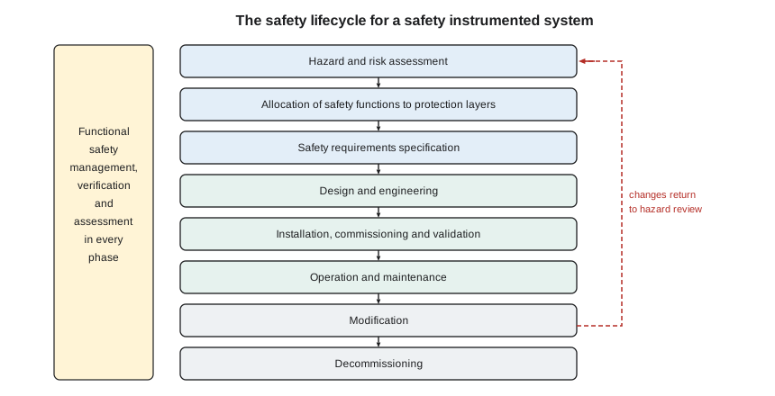
IEC 61511 organizes SIS work into a safety lifecycle that runs from hazard analysis to decommissioning. The main phases are:
- Hazard and risk assessment: identify hazardous events and the risk reduction each needs, usually through HAZOP and LOPA (PWR-340).
- Allocation of safety functions to protection layers, deciding which hazards need a SIF and what integrity each must achieve.
- Safety requirements specification (SRS): a document that defines each SIF completely, including the process demand, the trip set point and response time, the safe state, the required integrity, the proof test interval, the bypass rules, the reset requirements and the spurious trip limit.
- Design and engineering of the hardware and application program to meet the SRS.
- Installation, commissioning and validation: confirming, before startup, that the installed SIS meets the SRS, including a full functional test of every SIF.
- Operation and maintenance, including proof testing, bypass control and the recording of demands and failures.
- Modification under management of change, returning to the appropriate earlier phase, and eventually decommissioning.
Running through every phase are functional safety management (named responsibilities and competence), verification that each phase's outputs are correct, and functional safety assessments by people independent of the design team at stated points in the lifecycle.
Safety integrity levels
Each SIF is assigned a safety integrity level (SIL) according to the risk reduction it must provide. For functions that are demanded rarely, less than once a year (the low demand mode typical of process trips), the SIL is defined by the average probability of failure on demand, PFD avg, which is the chance that the function will fail to act when called upon. The risk reduction factor (RRF) is its reciprocal.
| SIL | PFD avg (low demand) | Risk reduction factor |
|---|---|---|
| 1 | 0.1 down to 0.01 | 10 to 100 |
| 2 | 0.01 down to 0.001 | 100 to 1,000 |
| 3 | 0.001 down to 0.0001 | 1,000 to 10,000 |
| 4 | 0.0001 down to 0.00001 | 10,000 to 100,000 |
The deaerator trip, credited at 0.01 in the LOPA, sits exactly on the boundary between SIL 1 and SIL 2. To deliver what the LOPA assumed, the function must achieve a PFD avg of 0.01 or better, which in practice means designing it to SIL 2. Achieving a SIL involves three things: the calculated PFD avg must meet the target, the architecture must have enough hardware fault tolerance for the SIL, and the devices and software must be developed or proven to avoid systematic failures such as design errors.
Calculating PFD
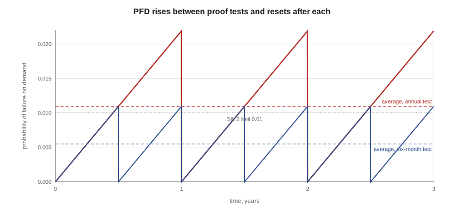
A device's dangerous failures are divided into those detected by diagnostics, which are repaired quickly, and dangerous undetected failures, with rate λ_DU, which stay hidden until a proof test finds them. If a proof test every T_I hours finds and repairs every hidden failure, the probability that a single device has failed undetected rises from zero just after a test to about λ_DU T_I just before the next, and its average over the interval is:
For a SIF built from a sensor, a logic solver and a final element in series, all of which must work, the PFDs add:
Worked problem
The deaerator low-low level trip
The proposed SIF uses one level transmitter with λ_DU = 5 × 10⁻⁷ per hour, a certified safety logic solver with PFD avg 1 × 10⁻⁴, and as final element the trip contacts and starters of both feed pumps, treated as one element with λ_DU = 2 × 10⁻⁶ per hour (typical values for illustration). With an annual proof test (T_I = 8,760 h), what is the PFD avg, and does it meet the LOPA's 0.01? What if the test interval is six months?
Show solution
- Sensor:
- \[\frac{5 \times 10^{-7} \times 8{,}760}{2} = 2.19 \times 10^{-3}\]
- Final element:
- \[\frac{2 \times 10^{-6} \times 8{,}760}{2} = 8.76 \times 10^{-3}\]
- Total with the logic solver:
- \[PFD = 2.19 \times 10^{-3} + 1 \times 10^{-4} + 8.76 \times 10^{-3} = 1.11 \times 10^{-2}\]
- With a six-month test (T_I = 4,380 h):
- \[PFD = 1.10 \times 10^{-3} + 1 \times 10^{-4} + 4.38 \times 10^{-3} = 5.58 \times 10^{-3}\]
Answer: With annual testing the function reaches only 0.011, slightly worse than the 0.01 the LOPA credited, and it falls in SIL 1 (risk reduction about 90). Testing every six months brings it to about 0.0056 (risk reduction about 180), which meets the target and falls in SIL 2. The final element dominates, as it usually does: valves and motor starters fail more often than transmitters.
A shorter test interval is one way to improve a function; redundancy is the other. With two final elements in a one-out-of-two (1oo2) arrangement, either of which can achieve the safe state, both must fail before the function fails. If the two were truly independent, the PFD of the pair would be roughly (λ_DU T_I)² / 3, far smaller than for one. But two identical devices in the same service share common-cause failures: the same wrong calibration, the same corrosion, the same maintenance error. Common cause is modeled with a factor β, the fraction of failures that strike both together, and it usually dominates.
Worked problem
Redundant final elements
In the deaerator SIF, the final element is changed to two independent trip paths, one to each feed pump's starter, in 1oo2, each with λ_DU = 2 × 10⁻⁶ per hour, β = 0.1 and an annual test. What is the final element PFD now, and the PFD of the whole function?
Show solution
- \[\frac{(0.01752)^2}{3} = 1.02 \times 10^{-4}\]
- \[0.1 \times \frac{2 \times 10^{-6} \times 8{,}760}{2} = 8.76 \times 10^{-4}\]
- \[PFD_{final} \approx 9.8 \times 10^{-4}\]
- \[PFD_{SIF} \approx 2.19 \times 10^{-3} + 1 \times 10^{-4} + 9.8 \times 10^{-4} = 3.27 \times 10^{-3}\]
Answer: Redundancy cuts the final element's contribution by about a factor of nine, and the common-cause term is ten times the independent term. The whole function reaches about 0.0033 with annual testing, comfortably SIL 2. Now the single transmitter dominates, and the next improvement, if one were needed, would be there.
These simple formulas are suitable for understanding and for checking. A real SIL verification uses failure data from certified devices or plant records, includes diagnostic coverage, repair times, proof test coverage (no test finds every failure), and the time the function spends in bypass, and is usually done with software by a functional safety specialist.
Hardware fault tolerance and architecture
Common architectures are described by how many channels must act out of how many are installed:
- 1oo1: one channel; any dangerous failure defeats the function, any safe failure trips the plant.
- 1oo2: two channels, either can trip; good for safety, but either channel's safe failure causes a spurious trip.
- 2oo2: both must agree to trip; few spurious trips, but poorer safety than 1oo1 against dangerous failures, so it is rarely used for protection alone.
- 2oo3: two of three must agree; good for both safety and availability, and common for transmitters on large plants, often with a median selection for control.
IEC 61511 sets a minimum hardware fault tolerance for each SIL, meaning the number of faults the architecture can tolerate and still perform the function. SIL 1 and most SIL 2 functions can be single channel with suitable devices, while higher SILs need redundancy. The SIS logic solver for SIL 2 and above is normally a certified safety PLC, not a general-purpose controller.
Proof testing
A proof test is a periodic test designed to reveal the dangerous undetected failures that diagnostics cannot. A good proof test exercises the whole function, from a real or simulated process input through the logic to the final element moving to its safe state, and confirms the response time and the trip set point. A partial test, such as injecting a signal at the transmitter's output instead of changing the level, has lower proof test coverage, and the uncovered failures accumulate over the device's life until a full test or replacement.
The proof test procedure belongs in the SRS, its interval in the PFD calculation, and its results in the SIS records. A failed proof test is a found failure, and the plant must record it, repair it promptly, consider whether other similar devices are affected, and review whether the assumed failure rate was realistic. A plant that never finds a failed device on proof tests may be testing very good equipment, or may be running tests that cannot find anything.
Bypasses, overrides and spurious trips
Every SIS needs a way to bypass a function for testing and maintenance, and every bypass is a period in which the protection is gone. IEC 61511 requires bypasses to be controlled: authorized by a named person, alarmed and displayed, time-limited, compensated by other measures such as continuous attendance or manual monitoring, and recorded. The time a function spends in bypass adds directly to its unavailability: 48 hours a year in bypass is about 0.0055 of the year, comparable to the whole PFD target of the deaerator trip.
Spurious trips, where the SIS shuts the plant down when there is no real demand, are safety problems too. Each trip is an upset with its own risk, at Cantwell a loss of steam to a seniors' residence in January, and a SIF that trips spuriously teaches operators to distrust it and to bypass it. The SRS should state the maximum acceptable spurious trip rate, and the architecture should be chosen to meet both the safety target and that rate.
Reset is the last design decision. After a trip, the SIS must stay tripped until the cause is cleared and a person deliberately resets it; a function that resets itself when the level recovers could restart the feed pumps into a still-dry suction. The SRS for the deaerator trip will call for a manual reset at the pump starters after a level check.
The BMS as a SIS
A boiler's burner management system is a safety instrumented system in everything but name. Its functions, such as low-water fuel cutoff, flame failure trip, high steam pressure trip, low fuel pressure, low combustion air and purge interlocks, are exactly the protective functions IEC 61511 describes. The boiler codes and combustion standards (NFPA 85 and CSA B149.3 for larger units, CSD-1 for smaller ones, PWR-330) set their own requirements, which govern the BMS design. Many plants now also apply the IEC 61511 lifecycle to their BMS, especially for SIL verification, proof testing and management of change.
Cantwell's BMSs are separate safety-rated controllers, one per boiler, with low-water cutouts that are tested on a schedule and logged. Grazyna's view is that the same discipline should cover them as will cover the new deaerator trip: a written SRS for each function, a proof test procedure with its interval, and a register of every bypass. "The BMS is where most of our risk sits," she said, "and we've treated it as a piece of equipment rather than a set of promises."
Common mistakes
MistakeUsing a DCS transmitter for both control and a trip.
InsteadKeep the SIF's sensor independent of the BPCS loop it protects.
MistakeAssuming redundancy makes common cause disappear.
InsteadInclude a β factor; common cause usually dominates redundant pairs.
MistakeLengthening the proof test interval without recalculating PFD.
InsteadThe test interval is part of the SIL calculation.
MistakeLeaving a SIF in bypass without a time limit or compensating measures.
InsteadControl, alarm, limit and record every bypass.
MistakeDesigning a trip that resets itself.
InsteadRequire a deliberate manual reset after the cause is cleared.
MistakeTreating a SIL as a property of a device.
InsteadA SIL belongs to the whole function: sensor, logic, final element and testing.
Summary and key terms
- A SIS takes the process to a safe state on a dangerous condition; it is dormant and its dangerous failures are hidden, so it must be independent of the BPCS.
- IEC 61511 (with CSA and ANSI/ISA adoptions) defines a safety lifecycle from hazard analysis through the SRS, design, validation, operation, modification and decommissioning.
- SIL in low demand mode is set by PFD avg: SIL 1 from 0.1 to 0.01, SIL 2 from 0.01 to 0.001, SIL 3 from 0.001 to 0.0001.
- PFD avg ≈ λ_DU T_I / 2 per device, summed over sensor, logic and final element; shorter tests and redundancy reduce it, but common cause limits redundancy.
- Proof tests must reveal hidden failures; bypasses must be controlled and counted; spurious trips and resets are design requirements too.
- A BMS is a set of safety instrumented functions governed by the combustion codes and increasingly managed with the IEC 61511 lifecycle.
- Safety instrumented system
- Sensors, logic solver and final elements that take a process to a safe state on a dangerous condition.
- Safety instrumented function
- One protective function of a SIS against one hazardous event.
- Safety integrity level
- A level from 1 to 4 defining the risk reduction a SIF must provide.
- Probability of failure on demand
- The average chance that a protective function will fail when called on.
- Safety requirements specification
- The document that defines each SIF completely.
- Proof test
- A periodic test designed to reveal dangerous undetected failures.
- Common-cause failure
- A failure that defeats redundant channels at the same time.
- Spurious trip
- A shutdown caused by the SIS when there is no real demand.
- Hardware fault tolerance
- The number of faults an architecture can tolerate and still perform its function.
Practice problems
Work each problem on paper first, then reveal the answer to check.
A valve has λ_DU = 3 × 10⁻⁶ per hour and is tested yearly. PFD avg?
Show answer
About 0.0131.
What SIL is a function with PFD avg 0.004?
Show answer
SIL 2.
What is the risk reduction factor of a function with PFD avg 0.002?
Show answer
500.
Which architecture gives good safety and few spurious trips with three transmitters?
Show answer
2oo3.
Lesson quiz · 5 questions
Score 60% or more to complete this lesson.
Create a free account to save your progress, take quizzes and earn a certificate.