
PWR-410 · Lesson 6 of 12 · 27 min
Advanced fluid mechanics
▶ Video coming soon A video version of this lesson is on the way.
Pilar had once watched a safety valve lift on boiler 3 during a pressure test, and had always remembered the noise: a roar that seemed far too loud for the size of the valve. Grazyna used it to open the sixth session. "That valve was passing steam at the speed of sound in its throat," she said. "Once a gas or vapor reaches that speed, the flow behaves differently from anything you learned for water in pipes. Tonight we look at compressible flow, at nozzles and choking, and then come back to liquids and the pumps that move them, which is where most of our own trouble comes from."
This lesson covers the energy equation for compressible flow, stagnation properties, the speed of sound and Mach number, flow through nozzles and the critical pressure ratio, choked flow through valves and orifices, flashing and two-phase flow, and then pump and fan laws, specific speed and net positive suction head, all at the level expected for Second Class.
The steady-flow energy equation for compressible flow
For steady flow of a fluid through a duct or nozzle with no heat transfer and no work, the steady-flow energy equation, neglecting changes in elevation, is:
with h in ft·lbf/lbm and V in ft/s, the kinetic energy term is V²/2g_c, where g_c = 32.174 lbm·ft/lbf·s². With enthalpy in Btu/lb, V = 223.8 √Δh gives the velocity in ft/s from an enthalpy drop in Btu/lb. For liquids at ordinary velocities, the kinetic energy is small and the familiar Bernoulli equation of PWR-310 is enough. For gases and steam at high velocity, the kinetic energy becomes comparable to the enthalpy change: in a turbine nozzle, the whole point is to turn enthalpy into velocity.
The stagnation enthalpy h₀ = h + V²/2 is the enthalpy a moving stream would have if it were brought to rest adiabatically. For an ideal gas, the corresponding stagnation temperature is T₀ = T + V² ÷ 2c_p. A thermometer in a fast gas stream reads close to the stagnation temperature, not the static temperature, because the gas slows down on its surface; at 656 ft/s in air, the difference is about 35.8 °F. Gas turbine and compressor test codes therefore specify how temperatures are measured and corrected.
Speed of sound and Mach number
Small pressure disturbances travel through a fluid at the speed of sound a. For an ideal gas it depends only on the gas and its absolute temperature:
In air at 59 °F, with k = 1.4 and R = 53.35 ft·lbf/lbm·°R, a = 1,116 ft/s; in gas turbine exhaust at 1,013 °F it is about 1,880 ft/s. For steam the same formula can be used approximately with k about 1.3 for superheated steam, or the speed can be found from the steam's properties. The Mach number is the ratio M = V ÷ a. Flow is subsonic below M = 1 and supersonic above it.
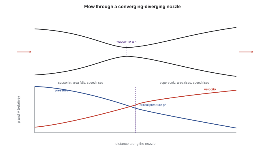
The behavior of the flow changes at M = 1. In subsonic flow, a converging passage accelerates the fluid and a diverging one slows it, as with water. In supersonic flow the reverse is true: a diverging passage accelerates it further, because the gas expands so rapidly as its pressure falls that the area must increase to pass the same mass. This is why the nozzles that produce supersonic steam in turbine impulse stages, and in steam jet air ejectors, are converging-diverging, with a narrow throat where M = 1.
Nozzles and the critical pressure ratio
Consider a converging nozzle fed from a large chamber at stagnation pressure p₀, discharging into a space at back pressure p_b. As p_b is lowered, the flow increases, until the velocity at the nozzle exit reaches the speed of sound. The pressure at the throat is then the critical pressure p*, and lowering the back pressure further has no effect on the flow: the nozzle is choked. For an isentropic expansion of an ideal gas or vapor following pv^n = constant:
| Fluid | Exponent n (typical) | Critical pressure ratio |
|---|---|---|
| Air and other diatomic gases | 1.4 | 0.528 |
| Superheated steam | 1.3 | 0.546 |
| Dry saturated steam | 1.135 | 0.577 |
Worked problem
A steam nozzle at Keswold's inlet conditions
Steam at 880 psia and 900 °F (h = 1,453.0 Btu/lb) expands isentropically in a nozzle. Find the exit velocity if the outlet pressure is 510 psia. Then find the critical pressure, and the throat velocity, specific volume and area for a flow of 1 lb/s, using IAPWS-IF97 properties.
Show solution
- \[h_2 = 1{,}380.0 \text{ Btu/lb at } 510 \text{ psia (742 °F)} \;\Rightarrow\; \Delta h = 73.0 \text{ Btu/lb}\]
- \[V_2 = 223.8 \sqrt{73.0} = 1{,}912 \text{ ft/s}\]
- \[p^* = 0.546 \times 880 = 480 \text{ psia}; \quad T^* = 726\ ^\circ\text{F}, \; V^* = 2{,}008 \text{ ft/s}, \; v^* = 1.398 \text{ ft}^3/\text{lb}\]
- \[A^* = \frac{\dot m\, v^*}{V^*} = \frac{1 \times 1.398}{2{,}008} = 0.000696 \text{ ft}^2 = 0.100 \text{ in}^2\]
Answer: The outlet pressure is above the critical pressure, so a converging nozzle is enough. Real nozzles lose some velocity to friction; a **velocity coefficient** of about 0.95 (typical) would give about 1,820 ft/s.
The mass flow through a choked nozzle depends only on the upstream stagnation conditions and the throat area. For an ideal gas:
The flow is proportional to the upstream absolute pressure and inversely proportional to the square root of the upstream absolute temperature. This is the basis of critical flow venturis used to calibrate gas meters, of the sizing equations for safety valves on gas and steam service, and of Napier's formula for steam, an empirical relation still widely used for the flow of saturated steam through an orifice discharging below the critical pressure:
Worked problem
A failed steam trap
A steam trap on a Cantwell main at 164.7 psia fails open, with a 1/8 in orifice discharging to atmosphere. Estimate the steam loss with Napier's formula.
Show solution
- \[A = \frac{\pi}{4} \times 0.125^2 = 0.01227 \text{ in}^2\]
- \[\dot m = \frac{0.01227 \times 164.7}{70} = 0.0289 \text{ lb/s} = 104 \text{ lb/h}\]
Answer: About 104 lb/h, or about 911,000 lb a year if it blew fully open all year. Real failed traps rarely pass their full orifice flow, which is why trap audits apply a factor; lesson 8 values the three traps found blowing in October.
Flashing and two-phase flow
When saturated or nearly saturated water flows to a lower pressure, part of it flashes to steam. The fraction flashed comes from an energy balance at constant enthalpy:
Condensate leaving a trap on Cantwell's mains, at 338.6 Btu/lb, flashes when it reaches the condensate system at atmospheric pressure: x = (338.6 − 180.1) ÷ 970.1 = 0.163. About 16 in 100 of its mass becomes steam, which occupies more than 260 times the volume of the liquid it came from. Condensate return lines must therefore be sized for a two-phase mixture, not for water, and flash tanks are used to separate the flash steam for low-pressure heating, as Cantwell's continuous blowdown flash tank does.
Two-phase flow takes several flow patterns depending on the velocities and the proportions of liquid and vapor: bubbly, slug, annular and mist flow in vertical pipes, and stratified, wavy and slug flow in horizontal ones. Slug flow, with plugs of liquid driven at high speed by the vapor, causes the hammering familiar in poorly drained steam lines and undersized condensate returns, and it can break fittings. Pressure drop in two-phase flow is much larger than for the liquid alone and is calculated with multiplier methods such as those of Lockhart and Martinelli. Flashing in a control valve can erode the trim, and if the pressure recovers downstream, the collapsing bubbles cause cavitation damage.
Pump laws and system curves
For a given centrifugal pump, the affinity laws relate flow Q, head H and power P to speed N (or, for geometrically similar pumps, to impeller diameter D at constant speed):
The pump operates where its head-flow curve crosses the system curve, the head the piping needs at each flow. In a closed circulating loop such as Cantwell's district hot water system, the system curve is pure friction, H = kQ², which passes through the origin and has the same shape as the affinity parabolas. Slowing the pump then moves the operating point down the system curve with the efficiency nearly unchanged, and power falls with the cube of speed. In an open system with a static head, such as a boiler feed pump lifting water into a drum at high pressure, much of the head is needed at any flow, so speed reduction saves far less, and the pump can reach a speed at which it no longer delivers at all.
Worked problem
Slowing hot water pump 2
Hot water circulating pump 2 delivers 630 gpm at 100 ft at 1,780 r/min on its variable-speed drive, in a closed loop. Find the water horsepower, and the flow, head and water horsepower at 80 in 100 speed. Find the brake horsepower at full speed if the pump is 0.78 efficient.
Show solution
- \[\text{WHP} = \frac{Q\,H}{3{,}960} = \frac{630 \times 100}{3{,}960} = 15.9 \text{ hp}, \qquad \text{BHP} = \frac{15.9}{0.78} = 20.4 \text{ hp}\]
- \[\text{At } 0.8 N: \; Q = 504 \text{ gpm}, \; H = 64 \text{ ft}, \; \text{WHP} = 15.9 \times 0.512 = 8.1 \text{ hp}\]
Answer: Twenty in 100 less flow for about half the power. The pump's 40 hp motor is well above its full-speed brake horsepower, a margin that allows for the loop's future extension to the seniors' residence's new wing.
The same laws apply to fans, with pressure in place of head, and they are the reason variable-speed drives on fans and pumps are among the most common energy measures. At reduced speeds the motor and drive efficiencies fall, so real savings are somewhat less than the cube law suggests, and at very low speeds a fan may stall or a pump may not overcome static head.
Specific speed characterizes the impeller type by its best-efficiency flow, head and speed:
Values below about 2,000 mean radial impellers, and very low values, below about 1,000, mean narrow impellers for high heads and low flows, such as boiler feed pumps, which therefore need several stages. Values from about 2,000 to 8,000 mean mixed-flow impellers, and higher still, axial-flow propellers for very large flows at low head, such as condenser circulating water pumps (typical ranges). Pump 2's value is 1,780 × √630 ÷ 100^0.75 = 1,413, a normal radial impeller.
Net positive suction head
A pump cavitates when the pressure at the impeller eye falls below the vapor pressure of the liquid, as PWR-210 and PWR-230 described for feed pump 2. The net positive suction head available (NPSHa) is the margin of the suction pressure above vapor pressure, expressed as head of the liquid at the pump suction:
where p_s is the absolute pressure on the liquid surface in the suction vessel, p_v the vapor pressure at the liquid temperature, z_s the height of the liquid surface above the pump centerline and h_f,s the friction loss in the suction piping. The pump maker states the NPSH required (NPSHr), conventionally the value at which the head falls by 3 in 100 because of cavitation, so a margin above NPSHr is needed to avoid damage; margins of 1.2 to 2 times, or a fixed allowance, are common in practice (typical), and more for high-energy pumps.
Worked problem
NPSH for a feed pump on a deaerator
The deaerator holds saturated water at 221 °F and about 17.6 psia. Its water level is 20 ft above the feed pump centerline, and the suction line loses 1.6 ft at full flow. Find NPSHa. Then find the loss of NPSHa if, during a sudden load increase, the deaerator pressure falls by 0.7 psi before the stored water cools.
Show solution
- \[p_s = p_v \;(\text{saturated}) \;\Rightarrow\; NPSH_a = 0 + 20 - 1.6 = 18.4 \text{ ft}\]
- \[\Delta NPSH = \frac{0.7 \times 144}{59.6} = 1.7 \text{ ft}\]
Answer: For a deaerator, the pressure term is zero because the water is saturated, so NPSHa is just the static height less friction. That is why deaerators are mounted high above the feed pumps, and why a falling deaerator pressure, which makes the water in the suction line hotter than the new saturation temperature, can make a pump cavitate even when the level is normal. A low level does the same, as feed pump 2 showed on October 27.
NPSHr rises with flow, roughly with the square of flow, so a pump running far out on its curve, beyond its best efficiency point, can cavitate with an NPSHa that is ample at design flow. Running far below the best efficiency point causes suction recirculation, which also damages impellers and is why feed pumps have minimum flow recirculation lines. Both effects explain why the operating point matters as much as the suction conditions.
Fluid mechanics in operating decisions
Grazyna ended the session with three questions she said she was asked every year: why the safety valve roars, why the condensate return hammers, and why the feed pump grinds when the deaerator pressure swings. Pilar could now answer all three in numbers. The valve roars because its throat is choked at sonic velocity; the return hammers because about a sixth of the condensate flashes and the line is sized for water; and the pump grinds because a saturated suction has no pressure margin, only height, and a falling pressure takes some of that height away.
Common mistakes
MistakeExpecting lower back pressure to increase the flow through a choked nozzle.
InsteadOnce the throat is sonic, flow depends only on upstream conditions and throat area.
MistakeSizing condensate returns for liquid flow.
InsteadAllow for flash steam; a few parts in 100 of steam by mass fill most of the pipe's volume.
MistakeApplying the cube law to pumps working against high static head.
InsteadSpeed reduction saves much less when much of the head is static.
MistakeThinking a deaerator's pressure helps the feed pump's NPSH.
InsteadThe water is saturated, so only the height above the pump, less friction, is available.
MistakeIgnoring flow when checking NPSH.
InsteadNPSHr rises with flow; check at the highest flow the pump will see.
Summary and key terms
- For compressible flow, h + V²/2 is constant along an adiabatic duct; stagnation temperature exceeds static temperature.
- The speed of sound in an ideal gas is √(kRT); flow behaves differently above and below Mach 1.
- A converging nozzle chokes below the critical pressure ratio: about 0.528 for air, 0.546 for superheated steam, 0.577 for saturated steam.
- Choked flow depends only on upstream pressure, temperature and throat area; Napier's formula estimates steam leaks.
- Flashing condensate forms about 16 parts in 100 of steam from Cantwell's main pressure to atmosphere.
- Affinity laws: flow ∝ N, head ∝ N², power ∝ N³; NPSHa from a deaerator is height less friction.
- Stagnation temperature
- The temperature a moving gas reaches when brought to rest adiabatically.
- Mach number
- The ratio of flow velocity to the local speed of sound.
- Critical pressure ratio
- The ratio of throat to inlet pressure at which a nozzle reaches sonic velocity.
- Choked flow
- Flow limited by sonic velocity at a throat, unaffected by further reduction of downstream pressure.
- Flash steam
- Steam formed when hot condensate or water is released to a lower pressure.
- Affinity laws
- Relations between speed, flow, head and power for centrifugal pumps and fans.
- Specific speed
- A number characterizing an impeller type from its best-efficiency flow, head and speed.
- NPSH available
- Suction pressure above vapor pressure, as head of liquid at the pump inlet.
Practice problems
Work each problem on paper first, then reveal the answer to check.
Air at 540 °R flows at 820 ft/s. Find its stagnation temperature (c_p = 0.240 Btu/lb·°F).
Show answer
540 + 820² ÷ (2 × 0.240 × 778.17 × 32.174) = 595.9 °R.
Find the critical pressure for superheated steam entering a nozzle at 290 psia.
Show answer
0.546 × 290 = 158 psia.
A pump delivers 800 gpm at 130 ft at 1,750 r/min. Find the flow and head at 1,400 r/min.
Show answer
640 gpm and 83.2 ft.
A tank of saturated water stands 13 ft above a pump, with 1.3 ft of suction friction. Find NPSHa.
Show answer
11.7 ft.
Lesson quiz · 5 questions
Score 60% or more to complete this lesson.
Create a free account to save your progress, take quizzes and earn a certificate.