
PWR-410 · Lesson 11 of 12 · 28 min
Advanced electrical systems
▶ Video coming soon A video version of this lesson is on the way.
Ruaridh Brasseur, the electrician who looks after Cantwell's motors and switchgear, joined the eleventh session at Grazyna's invitation. He brought the main transformer's test report, the capacitor bank drawings for the motor control centers and a copy of the generator capability curve Okonkwo had photographed at Keswold. "Power engineers and electricians look at the same equipment from opposite ends," Grazyna said. "Tonight you can each ask the other the questions you have been saving up." Pilar's first question was why Cantwell's capacitor banks were sized at exactly 125 kvar per motor control center.
This lesson covers three-phase power and power factor correction, transformer ratios, losses, efficiency and regulation, fault current, induction motor performance, synchronous machines including the generator power angle and reactive power control, and harmonics, at the level of Second Class electrotechnology.
Three-phase power and power factor
For a balanced three-phase load with line voltage V_L, line current I_L and power factor cos φ, the real, reactive and apparent powers are:
Power factor is the ratio P ÷ S. Induction motors draw lagging reactive power to magnetize their cores, so a plant full of motors runs at a lagging power factor, typically 0.75 to 0.85 without correction (typical). Reactive current does no useful work but flows in every cable, transformer and switch, adding to their losses and using their capacity, and utilities charge large customers for low power factor or for demand in kVA rather than kW. Capacitors supply leading reactive power locally, so the supply carries less.
Worked problem
Sizing the capacitor bank on MCC 2
Motor control center 2 carries 300 kW at a power factor of 0.80 at 480 V. Find the capacitor kvar needed to raise the power factor to 0.95, and the line current before and after.
Show solution
- \[\tan(\cos^{-1}0.80) = 0.750, \qquad \tan(\cos^{-1}0.95) = 0.329\]
- \[Q_C = 300 \times (0.750 - 0.329) = 126.4 \text{ kvar}\]
- \[I_{0.80} = \frac{300{,}000}{\sqrt{3} \times 480 \times 0.80} = 451.1 \text{ A}, \qquad I_{0.95} = \frac{300{,}000}{\sqrt{3} \times 480 \times 0.95} = 379.8 \text{ A}\]
Answer: 126 kvar, which is why each MCC has five automatically switched 25 kvar steps, 125 kvar in all. The current falls by about 16 in 100, and the losses in the feeder, which vary with the square of the current, fall to (0.80 ÷ 0.95)² = 0.71 of their former value.
Correction is switched in steps because the reactive demand varies with load; a fixed bank sized for full load would over-correct at light load, raising the voltage and producing a leading power factor. Capacitors must also be kept clear of resonance with the system's inductance at the harmonic frequencies produced by variable-speed drives, discussed below; where drives are many, detuned banks with series reactors are used. Capacitors store energy after disconnection and have discharge resistors; they must be verified discharged before work, as part of lockout.
Transformers
An ideal transformer changes voltage in the ratio of its turns, and current in the inverse ratio, so that the apparent power is the same on both sides: V₁ ÷ V₂ = N₁ ÷ N₂ = I₂ ÷ I₁. Cantwell's 2,500 kVA main transformer steps the utility's 13.2 kV down to 480 V, a ratio of 27.5.
Worked problem
Rated currents and available fault current
Find the rated currents on each side of the 2,500 kVA, 13.2 kV to 480 V transformer, and the available three-phase fault current on the 480 V side if the utility source is very strong and the transformer impedance is 5.75 in 100.
Show solution
- \[I_{HV} = \frac{2{,}500{,}000}{\sqrt{3} \times 13{,}200} = 109.3 \text{ A}, \qquad I_{LV} = \frac{2{,}500{,}000}{\sqrt{3} \times 480} = 3{,}007 \text{ A}\]
- \[I_{fault} \approx \frac{I_{LV}}{Z_{pu}} = \frac{3{,}007}{0.0575} = 52{,}300 \text{ A}\]
Answer: About 52 kA, the figure PWR-240 quoted. Every breaker and fuse on the 480 V bus must have an interrupting rating above this value, and it is the starting point for the arc flash study.
A real transformer has two kinds of loss. Core loss (no-load or iron loss), from hysteresis and eddy currents in the core, is present whenever the transformer is energized and is nearly constant. Copper loss (load loss), I²R heating in the windings, varies with the square of the load. Efficiency is greatest at the load at which the two are equal:
Worked problem
Efficiency of the main transformer
The test report gives a core loss of 4.5 kW and a full-load copper loss of 22 kW (typical for this size). Find the efficiency at 60 in 100 of rating and a power factor of 0.90, the load for maximum efficiency, and the all-day efficiency if the transformer runs 16 hours at 60 in 100 and 8 hours at 30 in 100 load, both at 0.90 power factor.
Show solution
- \[P_{out} = 0.6 \times 2{,}500 \times 0.90 = 1{,}350 \text{ kW}; \quad \text{losses} = 4.5 + 0.36 \times 22 = 12.42 \text{ kW}; \quad \eta = \frac{1{,}350}{1{,}362.4} = 0.9909\]
- \[x_{max\,\eta} = \sqrt{\frac{4.5}{22}} = 0.452\]
- \[E_{out} = 16 \times 1{,}350 + 8 \times 675 = 27{,}000 \text{ kWh}; \quad E_{loss} = 24 \times 4.5 + 16 \times 7.92 + 8 \times 1.98 = 250.6 \text{ kWh}; \quad \eta_{day} = 0.9908\]
Answer: About 0.991. Transformer efficiencies are high, but the core loss runs all year: 4.5 kW for 8,760 hours is about 39,400 kWh, which is why a transformer left energized with no load still costs money, and why efficiency standards for distribution transformers limit core loss.
Voltage regulation is the rise in secondary voltage from full load to no load, as a fraction of the full-load voltage. It is approximately the transformer's per-unit resistance and reactance weighted by the load's power factor: VR ≈ R cos φ + X sin φ. For an impedance of 5.75 in 100 with a reactance-to-resistance ratio of 6 (typical), R ≈ 0.95 in 100 and X ≈ 5.67 in 100, so at 0.90 lagging the regulation is about 0.95 × 0.90 + 5.67 × 0.436 = 3.3 in 100. Transformers have tap changers, usually off-load on plant transformers, to set the secondary voltage for the expected load; lower impedance improves regulation but raises fault current, a trade-off the designer must balance.
Induction motors
A three-phase induction motor's stator creates a magnetic field rotating at synchronous speed n_s = 120f ÷ p, where f is the frequency and p the number of poles: 3,600, 1,800 and 1,200 r/min for 2, 4 and 6 poles at 60 Hz. The rotor turns slightly slower; the difference, as a fraction of synchronous speed, is the slip s, which rises roughly in proportion to load up to rated torque. The rotor's power is divided so that the rotor copper loss is s times the power crossing the air gap, which is why a motor running at high slip runs hot.
Worked problem
The new forced draft fan motor
Boiler 2's new FD fan motor is rated 60 hp, 1,775 r/min, 460 V, full-load current 69 A, efficiency 0.945. Find the slip, the full-load torque, the electrical input and the power factor at full load.
Show solution
- \[s = \frac{1{,}800 - 1{,}775}{1{,}800} = 0.0139, \qquad T = \frac{5{,}252 \times 60}{1{,}775} = 178 \text{ lb·ft}\]
- \[P_{in} = \frac{60 \times 0.7457}{0.945} = 47.3 \text{ kW}, \qquad \cos\varphi = \frac{47{,}350}{\sqrt{3} \times 460 \times 69} = 0.86\]
Answer: A slip of 1.4 in 100 and a power factor of about 0.85, both normal for a premium-efficiency four-pole motor of this size. At part load the power factor falls, which is why lightly loaded motors drag a plant's power factor down.
An induction motor draws five to eight times its full-load current when started across the line (typical), at a low power factor, which dips the bus voltage and stresses the windings. Soft starters, such as the one on the new FD fan motor, and variable-speed drives limit the starting current. The torque-speed curve rises from locked-rotor torque through breakdown torque, the maximum, to zero at synchronous speed; the motor must develop enough torque at every speed to accelerate its load, which for a fan rises with the square of speed. Motor efficiency standards in both countries require premium-efficiency motors for most general-purpose sizes, and PWR-310 showed what the step from 0.920 to 0.945 is worth on the FD fan.
Synchronous machines
A synchronous machine has a rotor carrying a DC field winding, or permanent magnets, and turns at exactly synchronous speed. Run as a generator, its stator voltage is set by the field current, its real power output by the prime mover's torque, and its reactive power by the field current relative to the grid voltage. Run as a motor, it can be overexcited to supply reactive power while driving a load, which is why large synchronous motors on compressors are sometimes used for power factor correction, and a synchronous machine run without load purely for reactive power is a synchronous condenser.
Connected to a large grid, a generator's terminal voltage is fixed by the grid. In a simple model, the generator is an internal voltage E behind its synchronous reactance X_s. The real power it delivers depends on the power angle δ between E and the terminal voltage V:
Raising the prime mover's torque increases δ and the real power; raising the field current increases E and the reactive power output. The maximum real power for a given excitation, at δ = 90°, is the steady-state stability limit; beyond it the machine pulls out of step. Generators therefore have underexcitation limiters that stop the voltage regulator from lowering the field so far that the machine approaches this limit.
Worked problem
Keswold's steam turbine generator on October 28
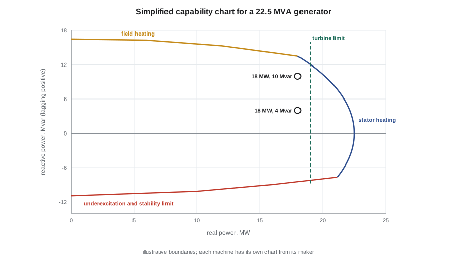
Keswold's steam turbine generator is rated 22.5 MVA. On the evening of October 28, at 18 MW, the grid operator asked it to raise its reactive output from 4 to 10 Mvar. Taking the terminal voltage as 1.0 per unit and a synchronous reactance of 1.8 per unit (typical for this kind of machine), find the internal voltage and power angle in each case, and the steady-state limit.
Show solution
- \[\text{At 4 Mvar: } I = \frac{18 - j4}{22.5} = 0.800 - j0.178; \quad E = 1 + j1.8\,(0.800 - j0.178) = 1.320 + j1.440 = 1.953 \angle 47.5^\circ\]
- \[\text{At 10 Mvar: } I = 0.800 - j0.444; \quad E = 1.800 + j1.440 = 2.305 \angle 38.7^\circ\]
- \[P_{max} = \frac{E V}{X_s} \times 22.5: \quad 24.4 \text{ MW at 4 Mvar}, \quad 28.8 \text{ MW at 10 Mvar}\]
Answer: Raising the reactive output raised the field, increased E by 18 in 100, reduced the power angle from 47.5° to 38.7° and raised the stability margin. Supplying reactive power is not free, though: the stator current rose from about 771 A to 861 A, and the field current rose too, so a generator's capability curve limits reactive output by stator heating and field heating.
The capability curve, the photograph Okonkwo had brought, shows the permitted combinations of real and reactive power. Its boundary is set by stator current at the rated MVA, by field current at high lagging reactive output, by the prime mover's maximum output, and by the underexcitation and stability limits at leading reactive output. Operators keep the operating point inside it.
Harmonics
Variable-speed drives, UPS rectifiers, LED lighting and other electronic loads draw current in pulses rather than smooth sine waves. The distorted current can be described as the fundamental at 60 Hz plus harmonics at whole multiples: a six-pulse drive produces mainly the 5th, 7th, 11th and 13th harmonics. Harmonic currents add heating in transformers and neutral conductors, can overheat or fail capacitor banks if they excite a resonance, cause nuisance tripping and interfere with metering and controls. Total harmonic distortion (THD) measures their size relative to the fundamental.
Limits at the point where a plant connects to the utility are commonly taken from IEEE 519, which sets voltage distortion limits for the utility and current distortion limits for the customer, scaled by the customer's size relative to the available fault current. Mitigation includes line reactors or DC chokes on drives, multi-pulse and active-front-end drives, passive tuned filters and active harmonic filters. Cantwell's growing number of variable-speed drives, including the one on hot water pump 2, was one reason Ruaridh recommended that any new capacitor steps be of the detuned type.
Bringing it together
Pilar's answer to her own first question was in her notes by the end of the session: the capacitor steps were sized from the MCC load and its uncorrected power factor, 126 kvar to reach 0.95, rounded to five standard 25 kvar steps so the controller could follow the load. Ruaridh's question to her had been why the plant cared about a few points of power factor when the motors ran just the same. She had answered it with the feeder loss ratio, 0.71, and the demand charge on the bill.
Common mistakes
MistakeCorrecting power factor with one fixed capacitor bank sized for full load.
InsteadSwitch it in steps; a fixed bank over-corrects and raises voltage at light load.
MistakeIgnoring harmonics when adding capacitors.
InsteadCheck for resonance; use detuned banks where drives are many.
MistakeThinking a lightly loaded transformer costs nothing.
InsteadCore loss runs whenever it is energized.
MistakeExpecting a generator's reactive output to be free.
InsteadIt raises stator and field current and is limited by the capability curve.
MistakeEquating rated slip with good condition.
InsteadHigh slip at a given load means more rotor loss; compare with the nameplate and check supply voltage.
Summary and key terms
- P = √3 V I cos φ; capacitor kvar = P (tan φ₁ − tan φ₂); feeder losses fall with the square of current.
- Cantwell's 2,500 kVA transformer: 3,007 A at 480 V and about 52 kA available fault current at 5.75 in 100 impedance.
- Transformer efficiency is greatest where copper loss equals core loss; regulation ≈ R cos φ + X sin φ.
- Induction motor speed = synchronous speed × (1 − s); synchronous speed = 120f ÷ p.
- Generator real power = EV sin δ ÷ X_s; field current controls reactive power and stability margin.
- Harmonics from drives heat equipment and can resonate with capacitors; IEEE 519 sets common limits.
- Power factor
- The ratio of real power to apparent power.
- Reactive power
- Power that oscillates between source and load to magnetize equipment, measured in var.
- Core loss
- Transformer loss from hysteresis and eddy currents in the core, present whenever energized.
- Voltage regulation
- The change in a transformer's secondary voltage from full load to no load.
- Slip
- The difference between synchronous and rotor speed of an induction motor, as a fraction of synchronous speed.
- Power angle
- The angle between a synchronous generator's internal voltage and its terminal voltage.
- Synchronous condenser
- A synchronous machine run without mechanical load to supply or absorb reactive power.
- Total harmonic distortion
- The size of the harmonic content of a waveform relative to its fundamental.
Practice problems
Work each problem on paper first, then reveal the answer to check.
A 400 kW load runs at 0.75 power factor. Find the kvar to correct it to 0.95.
Show answer
400 × (0.882 − 0.329) = 221 kvar.
Find the rated secondary current of a 1,500 kVA transformer at 480 V.
Show answer
1,804 A.
A transformer has 3 kW core loss and 12 kW full-load copper loss. At what load is it most efficient?
Show answer
√(3 ÷ 12) = 0.5 of rating.
A six-pole 60 Hz motor runs at 1,170 r/min. Find its slip.
Show answer
(1,200 − 1,170) ÷ 1,200 = 0.025.
Lesson quiz · 5 questions
Score 60% or more to complete this lesson.
Create a free account to save your progress, take quizzes and earn a certificate.