
PWR-410 · Lesson 5 of 12 · 27 min
Heat exchanger design and performance
▶ Video coming soon A video version of this lesson is on the way.
In October, Fenella's crew had opened Cantwell's plate heat exchanger 2 and cleaned scale from its plates, after Lorne noticed that the district hot water leaving it was running about 5 °F colder than it should. PWR-230 recorded the job. Grazyna brought the before-and-after log sheets to the fifth session. "You can tell the crew the exchanger was dirty," she said to Pilar. "At Second Class you should be able to tell them how dirty, in numbers, from the temperatures alone, and how long it will be before it needs cleaning again."
This lesson covers the overall heat transfer coefficient and fouling, the log mean temperature difference method and its correction factor for multipass and crossflow exchangers, the effectiveness-NTU method, the main exchanger types used in plants, and how exchanger performance is monitored and judged.
The overall heat transfer coefficient
Heat passing from a hot fluid to a cold one through a wall meets several resistances in series: the film on the hot side, any fouling on the hot side, the wall, any fouling on the cold side, and the film on the cold side. Their sum, per unit area, is the reciprocal of the overall heat transfer coefficient U:
for a thin flat wall. For tubes, each resistance is referred to the same area, usually the outside area, by multiplying the inside terms by the ratio of outside to inside diameter. The film coefficients h depend on the fluid, its velocity and whether it is boiling or condensing; typical values range from 2 to 9 Btu/h·ft²·°F for low-pressure gases, through 90 to 1,760 Btu/h·ft²·°F for liquids, to 880 to 8,800 Btu/h·ft²·°F for condensing steam (typical). The largest resistance controls: in a gas-to-liquid exchanger such as an economizer, the gas film controls, which is why economizer tubes carry fins on the gas side.
Worked problem
U for a steam-heated tube
Steam condenses on the outside of a thin steel tube (film coefficient 1,760 Btu/h·ft²·°F) and heats water inside (880 Btu/h·ft²·°F). The wall is 0.065 in thick with a conductivity of 26 Btu/h·ft·°F. Treating the wall as flat, find U clean, and with a water-side fouling resistance of 0.001 h·ft²·°F/Btu.
Show solution
- \[\frac{1}{U} = \frac{1}{1{,}760} + \frac{0.065/12}{26} + \frac{1}{880} = 0.001913 \;\Rightarrow\; U = 523 \text{ Btu/h}\cdot\text{ft}^2\cdot{}^\circ\text{F}\]
- \[\frac{1}{U_f} = 0.001913 + 0.001 = 0.002913 \;\Rightarrow\; U_f = 343 \text{ Btu/h}\cdot\text{ft}^2\cdot{}^\circ\text{F}\]
Answer: A fouling layer that adds less than one part in two to the resistance cuts the coefficient by more than a third. In clean, high-coefficient exchangers, fouling dominates performance.
Fouling
Fouling is any deposit that adds resistance: scale from hardness salts, corrosion products, biological growth in cooling water, sludge, oil films, or soot and ash on fire-side surfaces. It is described by a fouling resistance R_f, also called a fouling factor, with units of h·ft²·°F/Btu. A designer adds an allowance for fouling to the clean resistances, so the exchanger has more area than it needs when clean; the allowance comes from experience with the fluids and from tables such as those of TEMA, the Tubular Exchanger Manufacturers Association, for shell-and-tube exchangers. Typical design allowances for treated cooling water are about 0.0005 to 0.001 h·ft²·°F/Btu (typical).
Too large an allowance is not conservative in every sense. It adds area and cost, and at the start of the exchanger's life the extra area overheats or overcools the product unless the flow is throttled; lower velocities then encourage faster fouling. Plate exchangers, whose high turbulence keeps deposits down, are normally designed with much smaller margins than shell-and-tube exchangers, often an extra area of 10 to 25 in 100 rather than a large fouling resistance (typical).
In service, the fouling resistance is found from the clean and fouled coefficients:
The log mean temperature difference
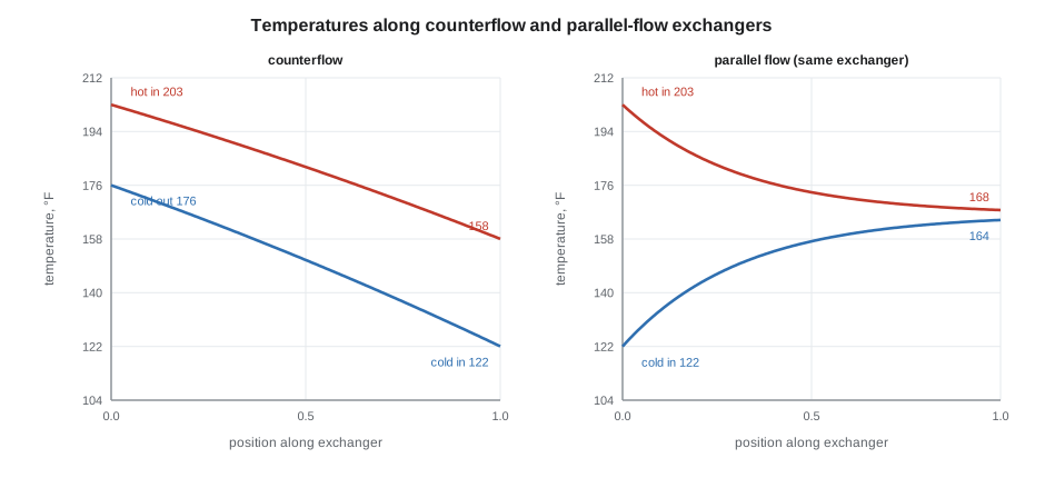
The heat transferred in an exchanger is Q = U A ΔT_m, where ΔT_m is a suitable mean temperature difference between the two fluids. For pure counterflow or pure parallel flow, with constant U and specific heats, the correct mean is the log mean temperature difference (LMTD):
where ΔT₁ and ΔT₂ are the temperature differences at the two ends. Counterflow, with the fluids entering at opposite ends, gives the largest LMTD for given terminal temperatures and allows the cold fluid to leave hotter than the hot fluid leaves, a temperature cross. Parallel flow gives a smaller LMTD and can never produce a cross. When one fluid condenses or boils at constant temperature, the arrangement does not matter.
Worked problem
Plate exchanger 1, clean
Cantwell's plate exchanger 1 transfers 3,412,000 Btu/h (1 MW) from the boiler loop, 203 °F to 158 °F, to the district loop, 122 °F to 176 °F, in counterflow, with 177 ft² of plate area. Find the LMTD and the clean overall coefficient.
Show solution
- \[\Delta T_1 = 203 - 176 = 27\ ^\circ\text{F}, \qquad \Delta T_2 = 158 - 122 = 36\ ^\circ\text{F}\]
- \[\Delta T_{lm} = \frac{36 - 27}{\ln(36/27)} = 31.28\ ^\circ\text{F}\]
- \[U = \frac{3{,}412{,}000}{177 \times 31.28} = 616 \text{ Btu/h}\cdot\text{ft}^2\cdot{}^\circ\text{F}\]
Answer: About 616 Btu/h·ft²·°F, the clean value PWR-310 recorded.
Correction factors for multipass and crossflow exchangers
Most shell-and-tube exchangers are not pure counterflow. In the common 1-2 exchanger, with one shell pass and two tube passes, the tube-side fluid flows one way and then back, so part of the exchanger is in parallel flow. The heat transfer is found by multiplying the counterflow LMTD by a correction factor F, read from charts or calculated from two ratios:
where T is the shell-side and t the tube-side temperature, and subscripts 1 and 2 are inlet and outlet. P is the thermal effectiveness of the tube side, and R is the ratio of heat capacity rates. F is always one or less. A common design rule is that F should not be below about 0.75 to 0.8 (typical); below that, the exchanger is working on a steep part of the curve where a small change in conditions causes a large change in F, and a second shell in series, or a different arrangement, is needed.
Worked problem
Sizing a lube oil cooler
A turbine lube oil cooler of the 1-2 shell-and-tube type must remove 477,700 Btu/h (140 kW), the bearing losses PWR-320 gave for Keswold's turbine. Oil (93 gpm, about 40,000 lb/h, c_p 0.48 Btu/lb·°F) enters the shell at 145 °F; cooling water enters the tubes at 86 °F and leaves at 98.6 °F. Find the oil outlet temperature, the correction factor and the area needed with a design U of 62 Btu/h·ft²·°F.
Show solution
- \[\Delta T_{oil} = \frac{477{,}700}{40{,}020 \times 0.48} = 24.9\ ^\circ\text{F} \;\Rightarrow\; T_2 = 120.1\ ^\circ\text{F}\]
- \[P = \frac{98.6 - 86}{145 - 86} = 0.214, \qquad R = \frac{145 - 120.1}{98.6 - 86} = 1.97 \;\Rightarrow\; F = 0.966\]
- \[\Delta T_{lm,cf} = \frac{(145 - 98.6) - (120.1 - 86)}{\ln(46.4/34.1)} = 39.95\ ^\circ\text{F}\]
- \[A = \frac{477{,}700}{62 \times 0.966 \times 39.95} = 200 \text{ ft}^2\]
Answer: About 200 ft². With a water-side fouling allowance the area rises by several percent more. The correction factor is close to one, so a single 1-2 shell is a good choice. Turbine oil coolers are installed in pairs, one in service and one on standby, with a transfer valve between them, so either can be cleaned with the turbine running.
Oil coolers are normally arranged so that the oil is at a higher pressure than the water. A tube leak then puts oil into the cooling water, where it can be seen, rather than water into the oil, where it would ruin the lubrication; PWR-230's turbine oil sample with about 600 ppm of water was a reminder of how much damage water in oil can do.
The effectiveness-NTU method
The LMTD method is direct when all four terminal temperatures are known, which is usually the case in design. When an existing exchanger must be rated, that is, when its outlet temperatures must be predicted for new inlet conditions or a new U, the LMTD method needs trial and error. The effectiveness-NTU method avoids it. It uses three dimensionless groups:
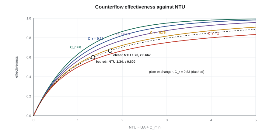
The effectiveness ε is the actual heat transfer divided by the maximum possible, which is what an infinitely long counterflow exchanger would transfer. For each flow arrangement there is a formula or chart relating ε to NTU and C_r. For counterflow:
When one fluid is condensing or boiling, its effective heat capacity rate is infinite, C_r = 0, and for every arrangement ε = 1 − e^{−NTU}. Effectiveness rises quickly with NTU at first and then flattens: doubling an exchanger's area when its NTU is already 3 or 4 gains little.
Worked problem
How dirty was plate exchanger 2?
Plate exchanger 2 is identical to exchanger 1. Before cleaning, with the same flows and inlet temperatures, its district outlet was 5 °F low: the district water was heated 49 °F instead of 54 °F. Find the clean and fouled effectiveness, the fouled U and the fouling resistance. The heat capacity rates are 75,830 Btu/h·°F on the boiler side and 63,190 Btu/h·°F on the district side.
Show solution
- \[C_{min} = 63{,}190 \text{ Btu/h}\cdot{}^\circ\text{F}, \quad C_r = 0.833, \quad NTU_{clean} = \frac{616 \times 177}{63{,}190} = 1.726, \quad \varepsilon_{clean} = \frac{54}{81} = 0.667\]
- \[\varepsilon_{fouled} = \frac{49}{81} = 0.605 \;\Rightarrow\; NTU = 1.364 \text{ (from the counterflow formula)}\]
- \[U_{fouled} = \frac{1.364 \times 63{,}190}{177} = 487 \text{ Btu/h}\cdot\text{ft}^2\cdot{}^\circ\text{F}\]
- \[R_f = \frac{1}{487} - \frac{1}{616} = 0.00043 \text{ h}\cdot\text{ft}^2\cdot{}^\circ\text{F/Btu}\]
Answer: The scale cut U by about 21 in 100 and the heat transferred from about 3.41 to 3.10 million Btu/h. Its resistance, about 0.0004 h·ft²·°F/Btu, was small in absolute terms, which is why plate exchangers are so sensitive to fouling: their clean resistance is small too.
Pilar plotted the exchanger's effectiveness each week from the log, and Grazyna suggested making it a standing trend in the distributed control system: with flow meters on both sides, effectiveness and U can be calculated every minute, and the rise of R_f over time shows when cleaning will pay. Keziah, the water treatment representative, had already been asked in October to review the district loop make-up, which was the likely source of the hardness.
Exchanger types in plants
Shell-and-tube exchangers are the workhorses: robust, suited to high pressures and temperatures, cleanable on the tube side by rodding or high-pressure water, and made in standard forms described by TEMA, with letter codes for the front head, shell and rear head types. Fixed tubesheet designs are cheapest but cannot accommodate large temperature differences between shell and tubes without an expansion joint; U-tube and floating head designs allow the tube bundle to expand freely and can be withdrawn for cleaning. Feedwater heaters, condensers, oil coolers and many process exchangers are of this kind.
Plate exchangers, made of pressed corrugated plates clamped in a frame with gaskets, give high coefficients and close temperature approaches in a small space and can be opened for cleaning, as Cantwell's were. Their limits are pressure, temperature and gasket compatibility; brazed and welded plate designs extend them. Air-cooled exchangers, finned tubes with fans, reject heat where water is scarce. Double-pipe exchangers suit small duties. Surface condensers, described in PWR-320, are a special shell-and-tube design with large shells for low-pressure steam, hotwells and air removal sections.
Choosing among them means balancing heat transfer, pressure drop, cost, cleanability and reliability. Pressure drop matters because it costs pumping power for the life of the exchanger: a design that saves a little area with high velocities may cost more in electricity than it saved in steel. Higher velocities, on the other hand, reduce fouling. Material selection must suit the fluids: stainless or titanium tubes in brackish cooling water, copper alloys for some fresh water services but not with ammonia, and carbon steel where the chemistry is controlled.
| Exchanger | Strengths | Limits | Plant examples |
|---|---|---|---|
| Shell-and-tube | High pressure and temperature, robust, many designs | Large, heavy; shell side hard to clean | Feedwater heaters, oil coolers, condensers |
| Gasketed plate | High U, close approach, compact, opens for cleaning | Gasket limits on pressure, temperature and fluids | District heating, chilled water, glycol loops |
| Brazed or welded plate | Compact, higher pressure than gasketed | Cannot be opened; chemical cleaning only | Refrigeration, small process duties |
| Air-cooled | No cooling water | Large area, fan power, weather | Engine radiators, process coolers |
| Finned tube (gas side) | Raises area where the gas film controls | Fouls in dirty gas | Economizers, HRSG sections, air heaters |
Monitoring performance
A good exchanger monitoring program records the four terminal temperatures and at least one flow, so the duty, the LMTD or effectiveness, and U can be calculated; the pressure drops on both sides, which rise as deposits build up; and the approach temperatures that matter for the plant, such as a condenser's backpressure or a heater's terminal temperature difference. U is best compared at the same flows, because film coefficients change with velocity; a rule of thumb is that a liquid film coefficient varies roughly with velocity to the power 0.8 (typical, for turbulent flow). The cost of cleaning is then weighed against the cost of the lost heat transfer, which for a condenser is lost megawatts and for a district exchanger is a higher boiler loop temperature and more pumping.
Common mistakes
MistakeUsing the arithmetic mean temperature difference.
InsteadUse the log mean; the arithmetic mean overstates the driving force when the end differences are unequal.
MistakeForgetting the correction factor for multipass shell-and-tube exchangers.
InsteadMultiply the counterflow LMTD by F, and avoid designs with F below about 0.8.
MistakeComparing U values taken at different flows.
InsteadFilm coefficients change with velocity; compare at the same flows or correct for them.
MistakeAdding a large fouling allowance as a safety margin.
InsteadOversizing lowers velocities, which can speed fouling, and overcools the product when clean.
MistakeArranging an oil cooler with water at the higher pressure.
InsteadKeep the oil at the higher pressure so a leak puts oil into the water, not water into the oil.
Summary and key terms
- 1/U is the sum of the film, wall and fouling resistances; the largest resistance controls.
- Q = U A ΔT_lm, with the log mean temperature difference; counterflow gives the largest LMTD.
- Multipass and crossflow exchangers need a correction factor F from P and R; keep F above about 0.8.
- The effectiveness-NTU method rates existing exchangers without trial and error.
- Fouling resistance R_f = 1/U_fouled − 1/U_clean; plate exchanger 2's scale was about 0.0004 h·ft²·°F/Btu.
- Monitor terminal temperatures, flows and pressure drops, and trend U or effectiveness to schedule cleaning.
- Overall heat transfer coefficient
- The rate of heat transfer per unit area per degree of temperature difference between two fluids.
- Fouling resistance
- The added thermal resistance of deposits on a heat transfer surface.
- Log mean temperature difference
- The effective mean temperature difference for counterflow or parallel flow exchangers.
- Correction factor F
- A factor applied to the counterflow LMTD for multipass or crossflow arrangements.
- Effectiveness
- Actual heat transfer divided by the maximum possible for the given inlet temperatures.
- NTU
- Number of transfer units, UA ÷ C_min, a measure of an exchanger's thermal size.
- Temperature cross
- A cold fluid leaving hotter than the hot fluid leaves, possible only with counterflow.
- TEMA
- The Tubular Exchanger Manufacturers Association, whose standards describe shell-and-tube exchanger types.
Practice problems
Work each problem on paper first, then reveal the answer to check.
Find the LMTD for end differences of 72 °F and 18 °F.
Show answer
54 ÷ ln 4 = 39.0 °F.
An exchanger's clean U is 440 Btu/h·ft²·°F and its fouled U is 352. Find R_f.
Show answer
1/352 − 1/440 = 0.00057 h·ft²·°F/Btu.
An exchanger has UA = 95,000 Btu/h·°F and C_min = 47,500 Btu/h·°F. Find NTU, and ε if one fluid is condensing.
Show answer
NTU = 2.0; ε = 1 − e^−2 = 0.865.
A counterflow exchanger must transfer 1,700,000 Btu/h with U = 210 Btu/h·ft²·°F and LMTD 36 °F. Find the area.
Show answer
1,700,000 ÷ (210 × 36) = 225 ft².
Lesson quiz · 5 questions
Score 60% or more to complete this lesson.
Create a free account to save your progress, take quizzes and earn a certificate.