
PWR-230 · Lesson 8 of 12 · 25 min
Heat exchangers and condensers
▶ Video coming soon A video version of this lesson is on the way.
On Saturday, October 10, 2026, plate heat exchanger 2 was opened for cleaning. It is one of the two exchangers that pass heat from Cantwell's hot water boilers to the district hot water loop, and for a month its district-side outlet had been running about 5 °F cooler than its twin at the same flow. Lorne Fitzwilliam isolated it, Fenella Thorncroft's crew loosened the tie bolts, and Tamar Ellingsen watched the plates come out one by one, each coated on the district side with a thin, rough, tan scale. "That's maybe half a millimeter of deposit," Lorne said, "and it's enough to cost us a tenth of this exchanger's output."
This lesson covers the heat exchangers found in plants: shell-and-tube and plate exchangers, how they are arranged, how their size and performance are calculated with the log mean temperature difference, how fouling degrades them, how surface condensers work with turbines, and how exchangers are isolated, cleaned and tested.
What a heat exchanger does
A heat exchanger transfers heat from one fluid to another through a wall, without mixing them. The rate of heat transfer depends on three things: how easily heat passes through the wall and the fluid films on each side, the area of the wall, and the temperature difference between the fluids. That is summed up in the basic heat exchanger equation:
where Q is the heat transfer rate in Btu/h, U the overall heat transfer coefficient in Btu/h·ft²·°F, A the heat transfer area in ft², and ΔT_lm the log mean temperature difference in °F.
U combines the resistances of the film on the hot side, the wall, the film on the cold side and any fouling on either surface. Turbulent, fast-moving fluids have thin films and high U; slow, viscous fluids or gases have thick films and low U. Fouling adds a resistance that grows over time.
Kinds of exchanger
- Shell-and-tube exchangers have a bundle of tubes inside a cylindrical shell. One fluid flows through the tubes, guided by the channel or head at each end, and the other flows around them in the shell, steered back and forth across the tubes by baffles. Variations include fixed tubesheet units, U-tube units (the bundle can expand freely and be pulled out, but the inside of the bends is hard to clean) and floating head units (one tubesheet can slide, and the bundle can be removed). They handle high pressures and temperatures and steam well.
- Plate exchangers are packs of thin corrugated stainless steel plates clamped between a fixed frame plate and a movable pressure plate by tie bolts. Gaskets around each plate direct the two fluids into alternate channels. The corrugations make the flow very turbulent, so U is high and the exchanger is compact. Gasketed plates can be opened for cleaning and more plates added; brazed plate exchangers are sealed units for smaller duties.
- Double-pipe exchangers, one pipe inside another, suit small duties and high pressures.
- Air-cooled exchangers and coils pass a fluid through finned tubes with air blown over them, like a car radiator or the coils in an air handler.
The district heating exchangers at Cantwell are gasketed plate units, each rated about 1 MW. Steam-to-water converters, shell-and-tube exchangers with steam in the shell, heat the domestic hot water and the building loops in many of the customer buildings.
Flow arrangement and the log mean temperature difference
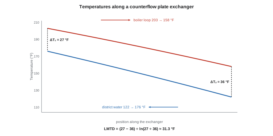
In parallel flow, both fluids enter at the same end and flow the same way. The temperature difference is large at the inlet and small at the outlet, and the cold fluid can never leave hotter than the hot fluid leaves. In counterflow, the fluids enter at opposite ends; the temperature difference is more even along the length, and the cold fluid can leave hotter than the hot fluid leaves. For the same temperatures, counterflow needs the least area, which is why plate exchangers and most shell-and-tube designs are arranged as close to counterflow as possible.
Because the temperature difference changes along the exchanger, the correct average to use is the log mean temperature difference:
where ΔT₁ and ΔT₂ are the temperature differences between the fluids at the two ends. For counterflow, ΔT₁ is the hot inlet minus the cold outlet and ΔT₂ the hot outlet minus the cold inlet. Shell-and-tube exchangers with several tube passes are neither true counterflow nor parallel flow, and a correction factor from the designer's charts is applied.
Worked problem
Sizing the district heating exchanger
Plate exchanger 2 is designed to transfer 3,412,000 Btu/h. Boiler-loop water enters at 203 °F and leaves at 158 °F; district water enters at 122 °F and leaves at 176 °F, in counterflow. The clean overall coefficient is 616 Btu/h·ft²·°F. What is the LMTD and the area needed?
Show solution
- End differences:
- \[\Delta T_1 = 203 - 176 = 27 \text{ °F} \qquad \Delta T_2 = 158 - 122 = 36 \text{ °F}\]
- LMTD:
- \[\Delta T_{lm} = \frac{27 - 36}{\ln(27 \div 36)} = \frac{-9}{-0.288} \approx 31.3 \text{ °F}\]
- Area:
- \[A = \frac{3{,}412{,}000}{616 \times 31.3} \approx 177 \text{ ft}^2\]
Answer: An LMTD of about 31.3 °F and about 177 ft² of plate area. The simple arithmetic mean of 27 and 36 °F would be 31.5 °F, close here because the end differences are similar; when they differ a lot, the arithmetic mean overstates the driving force and undersizes the exchanger.
Fouling and what it costs
Fouling is any deposit that builds up on a heat transfer surface: scale from hard water, corrosion products, biological slime, silt, oil or process deposits. It adds a layer of poor conductor to the wall and, in narrow plate channels, can also restrict flow and raise the pressure drop. Designers add a fouling allowance to the area, but an exchanger that fouls beyond it loses capacity.
Worked problem
Effect of fouling on plate exchanger 2
If fouling lowered plate exchanger 2's overall coefficient from 616 to 493 Btu/h·ft²·°F, (a) what would it transfer at the same LMTD of 31.3 °F, and (b) what LMTD would it need to transfer the full 3,412,000 Btu/h?
Show solution
- (a) Duty at the same LMTD:
- \[493 \times 177 \times 31.3 \approx 2{,}730{,}000 \text{ Btu/h}\]
- (b) LMTD needed for full duty:
- \[3{,}412{,}000 \div (493 \times 177) \approx 39.1 \text{ °F}\]
Answer: About 2,730,000 Btu/h at the same temperatures, a fifth less; or the boiler loop would have to run about 8 °F hotter to drive the full duty through. In practice the outlet temperature falls until the exchanger and the system settle at a lower duty, which is what Cantwell saw: the district outlet about 5 °F low.
Signs of fouling that operators watch for include a falling outlet temperature or a rising approach (the difference between one fluid's outlet and the other's inlet) at the same flows, a rising pressure drop across one side, and a hot side that must run hotter to hold the same duty. Trending these on the log, as Cantwell did, shows when to clean before the exchanger limits the plant on a cold day.
Prevention matters as much as cleaning. Good water treatment on the district loop (inhibitor, filtration, controlled make-up) and on cooling water (lesson 9) keeps scale and slime off the surfaces in the first place. The scale on exchanger 2 pointed to hard make-up water entering the district loop, and Grazyna asked Keziah Ostby to review the loop's make-up and treatment at her next visit.
Opening, cleaning and testing an exchanger
Lorne's job plan for exchanger 2 followed the plant's isolation procedure:
- Isolate both sides, hot and cold, with their inlet and outlet valves, then lock and tag them under the lockout procedure. Isolating only one side leaves the other side's pressure on the plates when the pack is opened.
- Drain and vent both sides, and confirm zero pressure on the gauges and by opening the drains. Hot water exchangers must also be cooled: water at 203 °F scalds.
- Record the tightening dimension, the distance between the frame and pressure plates, from the nameplate. Loosen the tie bolts evenly and in the sequence the manufacturer gives, so the pressure plate stays parallel.
- Remove the plates in order, keeping them in sequence; many plants number them. Clean them with soft brushes and a low-pressure wash or by soaking in the cleaning chemical the manufacturer approves for the deposit. Never use wire brushes or carbon steel tools on stainless plates; scratches and iron particles start corrosion.
- Inspect the plates for cracks, holes and thinning, and the gaskets for hardening, cracks and squeezing out of their grooves. Replace damaged gaskets.
- Reassemble in order, and tighten evenly to the nameplate dimension. Overtightening crushes gaskets and can crack plates; undertightening leaks.
- Pressure test as the procedure requires, then return the exchanger to service slowly, filling and venting each side and warming it gradually to avoid thermal shock.
Exchanger 2 went back into service at the end of the shift. At the same flows as before, its district outlet matched exchanger 1 within half a degree.
Shell-and-tube exchangers are cleaned by removing the heads and brushing, rodding or hydro-blasting the tubes, or by circulating a chemical cleaner. Leaking tubes are found by pressurizing the shell side with water or air and watching the tube ends, and are plugged at both ends or replaced. The number of tubes that can be plugged before the exchanger is too small for its duty is a design limit to record.
Pressure relief and tube failure
An exchanger's two sides often have different design pressures. If a tube or plate fails, the high-pressure fluid enters the low-pressure side, which may not be able to take it. The low-pressure side must therefore be protected by a relief valve or rupture disc sized for a tube rupture, where the design requires it.
A liquid-filled side that can be isolated while the other side is still hot also needs relief: trapped water heated by the other side expands with enormous force, enough to burst a shell or blow a gasket. This is called thermal relief, and it is one reason that, when an exchanger is taken out of service, the hot side is isolated first and the cold side last; when it is returned, the cold side is put in service first and the hot side last.
Surface condensers
A surface condenser is a large shell-and-tube exchanger that condenses the exhaust steam of a condensing turbine. Cooling water flows through the tubes; steam fills the shell and condenses on them. Because steam shrinks enormously when it condenses, the condenser creates a deep vacuum, and the lower the pressure, the further the steam expands in the turbine and the more work it does.
The condenser's pressure is set by the temperature at which the steam condenses, and so by the cooling water temperature and the condenser's cleanliness:
Worked problem
Temperature in a condenser
A turbine condenser operates at 2.07 inHg absolute. What is the condensing temperature, and what would a vacuum gauge read with the barometer at 29.92 inHg?
Show solution
- From the steam tables, saturation temperature at 2.07 inHg absolute (1.02 psia) is about 102 °F.
- Vacuum gauge reading:
- \[29.92 - 2.07 \approx 27.85 \text{ inHg vacuum}\]
Answer: About 102 °F, with the gauge reading about 27.85 inHg of vacuum. Cooling water entering at about 77 °F and leaving at about 91 °F could hold that. Warmer cooling water or fouled tubes raise the condensing temperature and the pressure together, and every inch of lost vacuum costs the turbine power.
Air leaks into any system under vacuum, through glands, joints and valve stems, and it does not condense. If it is not removed, it blankets the tubes and the pressure rises. Condensers therefore have air removal equipment: steam jet air ejectors, with their own small intercondenser and aftercondenser, or liquid ring vacuum pumps. The condensate collects in the hotwell at the bottom and is pumped away by condensate pumps, which have very little NPSH available because the condensate is at saturation at the condenser's low pressure.
A tube leak lets cooling water into the condensate. Because cooling water is far dirtier than boiler feedwater, even a small leak can contaminate the boilers quickly. Condensers are monitored by conductivity or sodium analyzers on the condensate; a rising reading calls for finding and plugging the leaking tubes.
Cantwell has no condensing turbine, since all its steam goes to customers and its one turbine exhausts to the deaerator, but it has several smaller condensers: the deaerator's vent condenser, the condensers of the chiller (lesson 10), and condensers in the steam-to-water converters of the customer buildings, where the steam condenses on the shell side. They work on the same principles.
Common mistakes
MistakeIsolating only one side of an exchanger before opening it.
InsteadIsolate, lock out, drain and vent both sides.
MistakeUsing the arithmetic mean temperature difference to size an exchanger.
InsteadUse the log mean temperature difference, with a correction factor for multipass designs.
MistakeCleaning stainless plates with a wire brush.
InsteadUse soft brushes and approved chemicals; scratches and iron particles cause corrosion.
MistakeTightening a plate pack until it stops leaking.
InsteadTighten evenly to the nameplate dimension; overtightening crushes gaskets.
MistakeIsolating the cold side of an exchanger while the hot side is still in service.
InsteadTake the hot side out first and put the cold side in first, or trapped water can burst the shell.
Summary and key terms
- Heat transfer in an exchanger is Q = U × A × LMTD; U combines film, wall and fouling resistances.
- Shell-and-tube exchangers suit high pressures and steam; gasketed plate exchangers are compact, efficient and easy to clean.
- Counterflow gives the largest temperature difference and the smallest area; LMTD = (ΔT₁ − ΔT₂) ÷ ln(ΔT₁ ÷ ΔT₂).
- Fouling lowers U, raises approach temperatures and cuts capacity; trend outlet temperatures and pressure drops.
- Isolate both sides, lock out, drain, vent and cool before opening; tighten plate packs to the nameplate dimension.
- Surface condensers create a vacuum set by the condensing temperature; air removal and tube leak monitoring keep them working.
- Overall heat transfer coefficient
- The rate of heat transfer per unit area per degree of temperature difference through a wall and its fluid films.
- Log mean temperature difference
- The correct average temperature difference for a heat exchanger, from the differences at its two ends.
- Counterflow
- An arrangement in which the two fluids flow in opposite directions.
- Fouling
- Deposits on a heat transfer surface that reduce heat transfer.
- Approach temperature
- The difference between one fluid's outlet temperature and the other fluid's inlet temperature.
- Plate heat exchanger
- An exchanger made of corrugated plates clamped together, with fluids in alternate channels.
- Surface condenser
- A shell-and-tube exchanger that condenses turbine exhaust steam under vacuum.
- Hotwell
- The bottom of a condenser, where condensate collects.
Practice problems
Work each problem on paper first, then reveal the answer to check.
A counterflow exchanger has end differences of 54 °F and 18 °F. What is the LMTD?
Show answer
About 32.8 °F.
With U = 210 Btu/h·ft²·°F and A = 215 ft², what does that exchanger transfer?
Show answer
About 1,480,000 Btu/h.
A condenser runs at 3.0 inHg absolute with the barometer at 29.92 inHg. What does the vacuum gauge read?
Show answer
About 26.9 inHg vacuum.
Why is the hot side of an exchanger isolated before the cold side?
Show answer
So that trapped cold-side water is not heated and over-pressurized.
Name two signs that an exchanger is fouling.
Show answer
Rising approach or falling outlet temperature at the same flows; rising pressure drop.
Lesson quiz · 5 questions
Score 60% or more to complete this lesson.
Create a free account to save your progress, take quizzes and earn a certificate.