
PWR-230 · Lesson 5 of 12 · 24 min
Air compressors and compressed air systems
▶ Video coming soon A video version of this lesson is on the way.
On Monday, September 21, 2026, Fenella Thorncroft, Cantwell's maintenance planner, came down to the compressor room with an ultrasonic leak detector in a padded case and asked Tamar Ellingsen to help with the autumn air survey. The two instrument air compressors sat side by side on their skids, the lead machine humming steadily, with the aftercooler, the receiver, the refrigerated dryer and the filters lined up along the wall. "Every valve actuator, damper drive and control in this plant runs on this air," Fenella said. "If it goes, the plant goes. And compressed air is the most expensive utility we make, so every leak costs real money."
This lesson covers how air compressors work and are controlled, how air is cooled, dried and filtered for instruments, how receivers are built and inspected, and how to estimate what a leak costs. PWR-120 lesson 11 introduced the instrument air system and the dryer drain failure of November 3; this lesson looks at the machines in more depth.
Why compressed air costs so much
Compressing air is an inefficient way to move energy. Most of the electrical energy that goes into a compressor becomes heat, removed by the aftercooler and the oil cooler, and only a small fraction is left as useful work in the air at the point of use. A typical plant air system needs about 18 kW of compressor power for every 100 cfm of free air at 100 psig. That makes air a poor choice for jobs a motor could do, and it makes leaks costly.
Free air means air at atmospheric conditions, before compression. Compressor capacities and leak rates are quoted as free air delivered, in cubic feet per minute (cfm or scfm).
Kinds of compressor
Compressors are divided, like pumps, into positive displacement and dynamic types.
- Reciprocating compressors use pistons in cylinders, with spring-loaded plate or reed valves. Single-acting pistons compress on one side; double-acting pistons compress on both sides. For pressures above about 100 psig, compression is usually split into two or more stages with an intercooler between them. Reciprocating compressors suit small and intermittent loads and high pressures.
- Rotary screw compressors trap air between two meshing helical rotors and squeeze it as the rotors turn. In oil-flooded screws, oil injected into the rotors seals, cools and lubricates them and is separated from the air afterward; oil-free screws use timing gears and coated rotors and cost more. Screws suit steady loads and are the most common plant air compressor today.
- Rotary vane compressors use sliding vanes in an off-center rotor; scroll compressors use two interleaved spirals. Both are found in smaller sizes.
- Centrifugal compressors are dynamic machines: impellers fling the air outward at high speed, usually in two or three stages with intercoolers. They suit large, steady flows.
Cantwell has two oil-flooded rotary screw compressors, each driven by a 30 hp motor and rated about 122 cfm at 100 psig. One is the lead machine and the other is the lag, and they swap roles every month.
Compression, heat and staging
Compression raises the air's temperature sharply. In a single stage at the ratio needed for plant air, the air would leave far too hot for the oil, valves and piping without cooling. The compression ratio is always worked with absolute pressures:
Worked problem
Compression ratio for plant air
Air is drawn in at atmospheric pressure, 14.7 psia, and delivered at 100 psig. What is the compression ratio? What would each stage's ratio be in a two-stage machine with equal ratios?
Show solution
- Discharge pressure, absolute:
- \[100 + 14.7 = 114.7 \text{ psia}\]
- Overall ratio:
- \[114.7 \div 14.7 \approx 7.8\]
- Each of two equal stages:
- \[\sqrt{7.8} \approx 2.8\]
Answer: An overall ratio of about 8, or about 2.8 per stage in a two-stage machine. Splitting the ratio and cooling the air between stages reduces the work needed and keeps discharge temperatures within limits. Oil-flooded screws manage a single stage because the injected oil absorbs the heat as it is made.
Every stage of a reciprocating compressor has its own relief valve, and the discharge of every compressor has a high temperature switch that shuts it down. A failed intercooler, dirty cooler fins or low oil in a screw machine show up first as rising discharge temperature. In reciprocating machines, very high discharge temperatures can ignite carbon deposits and oil vapor in the discharge line, which is one reason the right compressor oil, kept clean, matters.
Capacity control
Air demand changes constantly, and compressors match it in several ways:
- Start/stop: the motor stops when the pressure reaches its upper setting and restarts at the lower setting. Simple, but suitable only for small motors that can tolerate frequent starts.
- Load/unload: the motor keeps running, but the compressor's inlet valve closes and the machine idles unloaded until the pressure falls. An unloaded screw still draws a good part of its full power, so a long unloaded run wastes energy; most controls stop the motor after a set unloaded time.
- Modulation: the inlet valve throttles to match output to demand. Smooth, but inefficient at low loads.
- Variable speed drive: the motor speed changes to match demand, and power falls nearly in proportion. Usually the most efficient choice for a varying load.
With two machines, a lead-lag sequence runs the lead compressor first and starts the lag if pressure keeps falling. Cantwell's lead runs load/unload between about 100 and 110 psig; the lag cuts in at a lower setting. A lag compressor that keeps cutting in on a quiet day is a sign of a leak or an open drain, as PWR-120 lesson 11 showed.
Unloaders also let a compressor start unloaded, with no pressure to push against, so the motor can come up to speed easily.
Treating the air
Atmospheric air carries water vapor, dust and, in an oil-flooded machine, traces of oil. Instruments and valve actuators need air that is clean, dry and oil-free, and the treatment train does that:
- An intake filter keeps dust out of the compressor.
- An aftercooler cools the hot discharge air to within about 20 °F of the cooling air or water temperature. Most of the water vapor condenses here and is removed in a moisture separator.
- The receiver stores air, smooths pressure swings and lets more water settle out.
- A dryer lowers the air's pressure dew point, the temperature at which water would condense out of the air at line pressure. Refrigerated dryers, like Cantwell's, chill the air to about 37 °F, drain the water and reheat the air; they suit indoor piping that never gets colder. Desiccant dryers pass the air through beds of activated alumina or silica gel and reach pressure dew points of −40 °F or lower; they are needed where air lines run outdoors or through cold spaces. Membrane dryers suit small flows.
- Filters: a coalescing filter for oil aerosols and fine particles, and a particulate filter downstream of a desiccant dryer to catch dust from the beds.
- Drains on the separator, receiver, dryer and filters remove the condensate. Timed drains open for a few seconds on a schedule; zero-loss drains open only when condensate is present and waste no air. A drain stuck open, as at Cantwell on November 3, blows air continuously; a drain stuck shut lets water carry into the system.
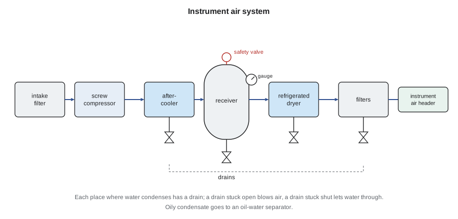
The condensate from an oil-flooded compressor contains oil, so it goes through an oil-water separator before it reaches the drain.
Air quality for instruments is usually specified by class under ISO 8573-1, which sets limits for particles, water and oil separately. The instrument manufacturers' requirements decide the class needed; the dryer and filters are chosen to meet it.
Air receivers
An air receiver is a pressure vessel, built to ASME Section VIII, Division 1, and stamped with the ASME certification mark. In Ohio, unfired pressure vessels above the size limits in the state rules are registered and inspected under the state boiler and pressure vessel program. The compressors themselves are not licensed in Ohio, although some states and cities do license compressor operators.
Every receiver has:
- A safety valve set at or below the vessel's maximum allowable working pressure and able to pass the full output of all the compressors that can feed it. No valve may be fitted between the receiver and its safety valve.
- A pressure gauge.
- A drain at the lowest point, opened regularly or fitted with an automatic drain. Water left in a receiver corrodes it from the inside.
- A nameplate with the maximum allowable working pressure and temperature, the design code and the registration number.
Operators check receivers on rounds for leaks, corrosion at the base and the drain, and safety valve condition. A safety valve on a receiver is tested by hand, with the pressure at least 75 in 100 of its set pressure, on the schedule the plant sets, and only replaced with a valve of the same set pressure and capacity.
Leaks and what they cost
In a typical plant air system, leaks waste a large share of the compressors' output. Leaks are found by listening on quiet nights, by spraying soapy water on joints, or best of all with an ultrasonic detector, which hears the hiss of escaping air above the plant's background noise.
Fenella and Tamar worked their way along the header from the receiver to the boiler front valve actuators. They found four leaks: a fitting on a damper actuator on boiler 2, a cracked push-in connector on the deaerator level valve, a weeping filter bowl gasket and a leaking hose on the soot-blower air connection. Each was tagged, logged with its location and estimated size, and entered as a work order. The leaks were each about the size of a hole 1/16 in across.
The flow through a hole depends on its size and the line pressure. At 100 psig, a sharp-edged hole of 1/16 in passes about 6.5 cfm of free air, and a hole of 1/8 in passes about four times as much. These are typical published values for well-rounded holes; real leaks vary.
Worked problem
Cost of four small leaks
Four leaks each pass about 6.5 cfm of free air, 26 cfm in all, at 100 psig. The compressors need about 0.18 kW per cfm, and the system is pressurized all year (8,760 h). At a sample electricity rate of 12 cents per kWh, what do the leaks cost a year?
Show solution
- Compressor power wasted:
- \[26 \times 0.18 = 4.68 \text{ kW}\]
- Energy a year:
- \[4.68 \times 8{,}760 \approx 41{,}000 \text{ kWh}\]
- Cost at the sample rate:
- \[41{,}000 \times 0.12 \approx 4{,}920 \text{ dollars}\]
Answer: About 41,000 kWh and roughly 4,900 dollars a year at the sample rate, for four leaks too quiet to hear over the plant's noise. They also use about a fifth of one compressor's capacity, which shortens the time the plant could ride through a compressor failure.
Leak repair is one of the cheapest energy savings in any plant. Others are lowering the header pressure to the least that the users need (a common rule of thumb is that each 2 psi of extra pressure costs about 1 in 100 of compressor power), shutting off air to equipment that is not running, and refusing to use compressed air for jobs like blowing down floors or cooling people.
Safety with compressed air
- Compressed air can enter the body through the skin or an opening and cause serious injury. Never point an air hose at anyone or use it to clean clothing or skin.
- Air used for cleaning must be reduced to a low pressure, through a nozzle that limits it, typically below 30 psi, with eye protection and chip guarding.
- Before working on a compressor, lock out its motor and its automatic restart controls, close and lock the isolating valve, and bleed off the stored pressure in the compressor, piping and any part of the receiver connected to the work. A compressor that has stopped on its pressure switch may start again at any moment.
- Hose connections should have safety couplings or whip checks so a hose that parts does not flail.
- Hot discharge piping and coolers burn; oil mist and condensate are slip hazards.
- Never tamper with a safety valve or plug its outlet.
Rounds on the compressors
Fenella showed Tamar what she looks for on a compressor round, beyond the log readings:
- Discharge pressure and temperature, oil level and oil filter differential pressure on the screw machines.
- Run and load hours on each machine, and the number of starts. A big increase in loaded hours with no change in plant load means more air is going somewhere.
- Dryer: the pressure dew point indicator, the refrigerant suction gauge, and that its drain cycles.
- Drains: listen for each automatic drain to cycle, and check that none blows continuously.
- Filters: differential pressure indicators. A rising drop wastes energy; a filter bowl full of liquid means a drain has failed.
- The receiver: drain it, check the gauge and look over the shell and the safety valve.
The round ended with the work orders entered. Fenella scheduled the repairs for the following week, and set a reminder to repeat the ultrasonic survey every spring and fall.
Common mistakes
MistakeWorking on a compressor after only switching it off.
InsteadLock out the motor and controls, isolate the air and bleed the stored pressure first.
MistakeLeaving a receiver drain closed for weeks.
InsteadDrain receivers regularly; standing water corrodes the shell.
MistakeUsing shop air at full pressure to blow dust off clothing.
InsteadNever; compressed air can enter the body. Use reduced pressure only for equipment, with guards.
MistakeRaising the header pressure to fix a weak air supply at one user.
InsteadFind the restriction or leak; extra pressure costs energy everywhere.
MistakeCalculating a compression ratio with gauge pressures.
InsteadUse absolute pressures.
Summary and key terms
- Compressed air is an expensive utility; most compressor input becomes heat.
- Reciprocating, rotary screw, vane, scroll and centrifugal compressors are the main types; screws dominate steady plant duty.
- Compression ratios use absolute pressures; staging with intercooling saves work and limits temperatures.
- Capacity control includes start/stop, load/unload, modulation and variable speed; lead-lag sequences share the load.
- Aftercoolers, receivers, dryers, filters and drains deliver clean, dry instrument air; refrigerated dryers reach about 37 °F pressure dew point, desiccant dryers much lower.
- Receivers are registered pressure vessels with safety valves, gauges and drains; leaks are found ultrasonically and cost thousands of dollars a year.
- Free air
- Air at atmospheric conditions, the basis for compressor capacity and leak rates.
- Compression ratio
- Absolute discharge pressure divided by absolute suction pressure.
- Intercooler
- A cooler between compressor stages that removes the heat of compression.
- Aftercooler
- A cooler after the final stage that cools the air and condenses most of its water.
- Pressure dew point
- The temperature at which water would condense from compressed air at line pressure.
- Load/unload control
- Capacity control in which a running compressor closes its inlet and idles when pressure is satisfied.
- Zero-loss drain
- A condensate drain that opens only when liquid is present, wasting no air.
- Air receiver
- A pressure vessel that stores compressed air and smooths pressure swings.
Practice problems
Work each problem on paper first, then reveal the answer to check.
A compressor delivers at 125 psig from atmospheric (14.7 psia). What is the compression ratio?
Show answer
About 9.5.
A leak of 13 cfm is fixed. At 0.18 kW per cfm, how much compressor power is saved?
Show answer
About 2.3 kW.
That saving runs 8,760 h a year at a sample rate of 12 cents per kWh. What is it worth?
Show answer
About 20,500 kWh, roughly 2,500 dollars a year.
Why are air lines that run outdoors in winter served by desiccant dryers?
Show answer
A refrigerated dryer's dew point of about 37 °F would let water condense and freeze in the cold lines.
What must be done before opening a compressor's discharge piping?
Show answer
Lock out the motor and controls, isolate it, and bleed off the stored pressure.
Lesson quiz · 5 questions
Score 60% or more to complete this lesson.
Create a free account to save your progress, take quizzes and earn a certificate.