
PWR-230 · Lesson 4 of 12 · 25 min
Centrifugal and positive displacement pumps
▶ Video coming soon A video version of this lesson is on the way.
On Thursday, September 17, 2026, Lorne Fitzwilliam handed Tamar Ellingsen a copy of the manufacturer's curve for boiler feed pump 2 and asked her to find out whether the pump was still on it. They read the suction and discharge gauges, the feedwater flow from the control screen and the motor current, then sat down in the control room with a calculator. "Pumps wear slowly," Lorne said. "Wear rings open up, impellers erode, and the pump makes a bit less head every year until one cold morning it cannot keep up. If you check it against its curve now and then, you see it coming."
This lesson covers the two families of pumps in a plant: centrifugal pumps, which make up nearly all of the water pumps at Cantwell, and positive displacement pumps, which meter chemicals, move fuel oil and lubricate machines. It explains pump curves, the best efficiency point, the affinity laws, NPSH and cavitation, shaft sealing, and why a positive displacement pump must always have a relief valve.
How a centrifugal pump works
A centrifugal pump has an impeller, a wheel of curved vanes, turning inside a casing. Liquid enters at the center of the impeller, the eye, and the vanes fling it outward, giving it velocity and pressure. The casing collects the liquid and slows it down, turning more of its velocity into pressure. Most casings are a volute, a spiral passage that widens toward the outlet; some pumps use a ring of fixed diffuser vanes around the impeller instead.
Other parts include:
- Wear rings: replaceable rings on the impeller and casing that form a close running clearance, limiting the leakage of liquid from the high-pressure side back to the eye. As they wear, the leakage rises and the pump's head and efficiency fall.
- The shaft, bearings and shaft seal (packing or a mechanical seal).
- Single-suction impellers take liquid in from one side; double-suction impellers take it from both sides, which halves the axial thrust and lowers the NPSH required.
- Multistage pumps, like Cantwell's boiler feed pumps, have several impellers in series on one shaft, each adding head.
A centrifugal pump makes head, not a fixed pressure. Head is the height of a column of the liquid that the pump could support, and it is the same for any liquid at the same speed. The pressure the pump develops depends on the liquid's density: the same pump makes less pressure on hot feedwater than on cold water.
In US units this is usually written H = 2.31 × Δp ÷ SG, with H in feet, Δp in psi and SG the specific gravity.
Pump curves
The manufacturer tests each pump model and publishes its performance curves at a given speed and impeller diameter:
- The head-capacity curve shows the head the pump develops at each flow. Head is highest at zero flow, the shutoff head, and falls as flow rises.
- The efficiency curve rises from zero to a peak and then falls. The flow at the peak is the best efficiency point (BEP).
- The power curve shows the shaft power needed. For most centrifugal pumps the power rises with flow, so the lowest power is at shutoff.
- The NPSH required curve, NPSHr, rises with flow.
The pump does not choose where it runs on its curve; the system does. The system curve is the head the piping system needs at each flow: the static head (the difference in elevation and pressure between the source and the destination), which does not change with flow, plus the friction head, which rises roughly with the square of the flow. The pump runs where its curve crosses the system curve.
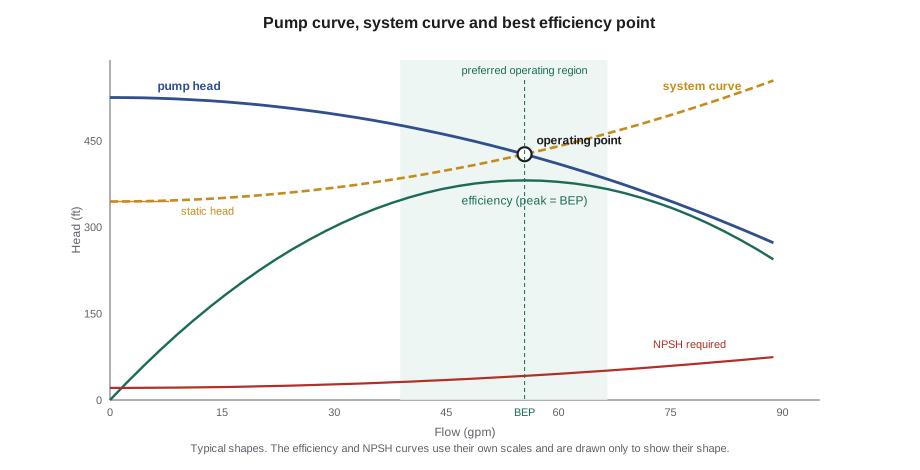
Closing a discharge valve adds friction and steepens the system curve, moving the operating point to the left, to lower flow and higher head. Opening a valve moves it to the right.
The best efficiency point and where to run
A pump is designed for its best efficiency point. Near it, the liquid flows smoothly through the impeller and casing and the radial forces on the impeller balance. Far from it, things go wrong:
- At low flow, well left of BEP, the liquid recirculates inside the impeller eye and the discharge, causing noise, vibration and damage that looks like cavitation. The radial force on the impeller rises, bending the shaft and wearing seals and bearings. Near shutoff, the energy put in by the motor heats the trapped liquid; hot feedwater can flash to steam and the pump can seize.
- At high flow, well right of BEP, the NPSH required rises, the pump may cavitate, and the motor may overload.
Most manufacturers state a preferred operating region, typically about 70 to 120 in 100 of BEP flow, and an allowable region beyond it. Boiler feed pumps often run at low flow when the boilers are lightly loaded, so they have a minimum flow recirculation line, with an orifice or an automatic recirculation valve, that sends enough water back to the deaerator to keep the pump above its minimum flow at all times.
Checking a pump against its curve
Worked problem
Is feed pump 2 on its curve?
Feed pump 2 is delivering 55 gpm of feedwater at 221 °F (specific gravity 0.95). Its suction gauge reads 14 psig and its discharge gauge 191 psig, with the gauges at the same height. The curve shows 430 ft at 55 gpm. What head is the pump making?
Show solution
- Pressure rise:
- \[\Delta p = 191 - 14 = 177 \text{ psi}\]
- Head:
- \[H = \frac{2.31 \times 177}{0.95} \approx 430 \text{ ft}\]
Answer: About 430 ft, right on the curve. Lorne logged it as the baseline for the heating season; a drop of more than about ten feet at the same flow would point to wear ring or impeller wear.
The check is only as good as the instruments. Gauges should be calibrated, at a known height (a difference in gauge height adds or subtracts head), and read when the flow is steady. Motor current gives a cross-check against the power curve.
The affinity laws
When a centrifugal pump's speed changes, its performance changes in a predictable way, described by the affinity laws. For a speed change from N₁ to N₂ with the same impeller:
Similar laws apply, approximately, to small trims of the impeller diameter. The cube law for power is why variable frequency drives on pumps and fans save so much energy.
Worked problem
Slowing a hot water circulating pump
Hot water circulating pump 2 delivers 630 gpm at 100 ft head and takes 40 hp at 1,780 r/min. Its drive slows it to 1,500 r/min. Estimate the new flow, head and power.
Show solution
- Speed ratio:
- \[1{,}500 \div 1{,}780 \approx 0.843\]
- Flow:
- \[630 \times 0.843 \approx 531 \text{ gpm}\]
- Head:
- \[100 \times 0.843^2 \approx 100 \times 0.710 \approx 71 \text{ ft}\]
- Power:
- \[40 \times 0.843^3 \approx 40 \times 0.598 \approx 23.9 \text{ hp}\]
Answer: A cut of about 16 in 100 in speed cuts the power by about 40 in 100. In a real system with static head the saving is smaller, because the pump must still overcome the static head, but on a closed hot water loop, where nearly all the head is friction, the affinity laws are a good estimate.
Pumps in series and parallel
- Two pumps in series add their heads at the same flow. Booster pumps and the stages of a multistage pump work this way.
- Two pumps in parallel add their flows at the same head. Because the system curve rises with flow, two identical pumps in parallel deliver less than twice the flow of one. Parallel pumps must have similar shutoff heads, or the weaker one can be pushed back to shutoff and overheat. Each parallel pump needs a check valve on its discharge.
NPSH and cavitation
PWR-210 lesson 10 introduced net positive suction head. At the pump's inlet, the liquid's pressure must stay above its vapor pressure, or it will flash into vapor bubbles. The NPSH available (NPSHa) is the margin the system provides; the NPSH required (NPSHr) is what the pump needs, from the manufacturer's test. NPSHa must exceed NPSHr with a margin.
When it does not, the pump cavitates: vapor bubbles form in the low-pressure eye of the impeller and collapse violently as they move into higher pressure. Cavitation sounds like gravel passing through the pump, the head and flow become unsteady, vibration rises, and over time the collapsing bubbles pit the impeller vanes near their leading edges into a spongy, honeycombed surface.
For a deaerator, the water is at its saturation temperature, so the pressure above the water adds nothing to the margin; only the height of the water above the pump, less the suction friction, keeps the water liquid. Cantwell's numbers from PWR-210 were:
- 30 ft of water above the pump at normal level, 21 ft at the low-level alarm.
- Suction friction of about 2.6 ft and an NPSHr of 10.5 ft.
- So NPSHa is about 27.4 ft at normal level and 18.4 ft at the low-level alarm, a margin of about 7.9 ft even at the alarm point.
Static margins like that can vanish in a transient. If the deaerator pressure drops suddenly, for example when a large cold make-up flow arrives, the water in the storage tank and suction line is briefly hotter than the new saturation temperature and flashes. That is what happened on October 27, when a low deaerator level and a pressure dip together made feed pump 2 cavitate (PWR-210 lesson 10).
Ways to protect a pump against cavitation include keeping the suction level up, keeping suction strainers clean, avoiding throttling on the suction side (suction valves are always fully open), keeping the pump near its BEP, and controlling deaerator pressure smoothly.
Shaft sealing: packing and mechanical seals
Where the shaft passes out of the casing, something must stop the liquid escaping. Two methods are used.
- Packing: rings of braided, lubricated fiber are pressed into a stuffing box around the shaft by an adjustable gland. Packing must leak a little, typically a steady drip of about 40 to 60 drops a minute on a pump of this size, because the leakage lubricates and cools the packing. A lantern ring in the middle of the packing may carry flushing or sealing water. Packing that is tightened until it stops leaking runs dry, overheats, and scores the shaft sleeve.
- A mechanical seal: a rotating face, fixed to the shaft, runs against a stationary face fixed to the gland plate, with a liquid film a few micrometers thick between them. Springs keep the faces together, and O-rings or bellows form the secondary seals. A good mechanical seal shows no visible leakage. A small flush of liquid, often from the pump's own discharge through a cyclone separator or cooler, keeps the faces cool and clean.
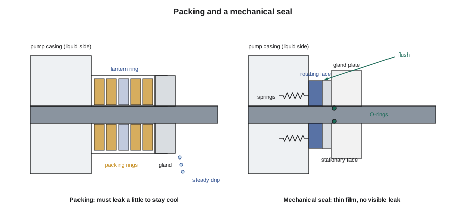
Mechanical seals use less power, need no adjustment and do not wear the shaft, which is why most modern pumps use them. Their weakness is that they fail suddenly, and they must never run dry: a few seconds without liquid can crack the faces. Before starting a pump with a mechanical seal, the casing must be full and vented. Hot water seals need their flush cooled, because water near its boiling point flashes across the faces.
When a packed pump leaks too much, the gland nuts are tightened evenly, a little at a time, with the pump running, and the leakage given time to settle before the next adjustment. When the gland reaches the end of its travel, the pump is taken out of service and repacked.
Starting and stopping a centrifugal pump
- Make sure the pump is full of liquid and vented. A centrifugal pump cannot lift liquid when it is full of air, and the seal may be damaged running dry.
- Open the suction valve fully.
- On most radial-flow pumps, start with the discharge valve closed or nearly closed, because power is lowest at shutoff, then open it within a minute or so. Feed pumps start with their minimum flow recirculation open.
- Never run any pump for long against a closed discharge with no recirculation: the liquid heats up and can flash.
- Check discharge pressure, motor current, seal or packing leakage, bearing temperatures and vibration.
- To stop, close the discharge valve partly (where the procedure says so) to avoid water hammer, stop the motor, and check the non-return valve has closed and the pump is not running backwards.
Positive displacement pumps
A positive displacement (PD) pump traps a fixed volume of liquid and pushes it out, once every stroke or revolution. Its flow is set by its speed and displacement and hardly changes with the discharge pressure. Kinds include:
- Reciprocating pumps: piston, plunger and diaphragm pumps. Chemical metering pumps, like Cantwell's sulfite and amine feed pumps, are small diaphragm or plunger pumps with an adjustable stroke length and speed.
- Rotary pumps: gear, screw, lobe and vane pumps. They move viscous liquids smoothly: fuel oil, lubricating oil, glycol.
The key difference from a centrifugal pump is what happens when the discharge is blocked. A centrifugal pump just runs back to its shutoff head. A PD pump keeps pushing the same volume, so the pressure rises until something gives: a pipe, a gasket, the pump casing or the driver. Therefore:
- Every PD pump needs a relief valve on its discharge, between the pump and the first valve that could be closed, set below the pressure rating of the weakest part of the system and sized to pass the pump's full flow. Many rotary pumps have one built in; the discharge of a relief valve should go back to the suction tank, not the pump suction, if the pump might run on it for long.
- A PD pump is started with its discharge valve open, never closed.
- Its flow is controlled by changing its speed or stroke, or by a bypass back to the suction source, never by throttling the discharge.
Reciprocating pumps also deliver a pulsing flow. Pulsation dampeners on the discharge smooth it, and backpressure valves keep a metering pump from siphoning when it discharges into a line at lower pressure.
Common mistakes
MistakeRunning a centrifugal pump for long against a closed discharge.
InsteadOpen the discharge or recirculation; the trapped liquid heats and can flash.
MistakeThrottling a pump's suction valve to reduce flow.
InsteadKeep suction valves fully open; throttle on the discharge or change speed.
MistakeTightening packing until it stops dripping.
InsteadPacking needs a steady drip to stay cool and lubricated.
MistakeStarting a positive displacement pump with its discharge closed.
InsteadStart PD pumps with the discharge open, and always protect them with a relief valve.
MistakeRunning a mechanical seal dry for a quick rotation check.
InsteadFill and vent the casing first; seconds dry can crack the faces.
Summary and key terms
- A centrifugal pump develops head; the pressure it makes depends on the liquid's density.
- The pump runs where its head-capacity curve crosses the system curve; it is happiest near its best efficiency point.
- Flow varies with speed, head with speed squared and power with speed cubed (the affinity laws).
- NPSH available must exceed NPSH required with a margin, or the pump cavitates; deaerator transients can remove the margin suddenly.
- Packing must drip to stay cool; mechanical seals run leak-free on a thin film and must never run dry.
- Positive displacement pumps deliver a fixed volume per stroke, start with the discharge open, and always need a relief valve ahead of the first closable valve.
- Impeller
- The vaned wheel of a centrifugal pump that gives the liquid velocity and pressure.
- Volute
- The spiral casing of a centrifugal pump that converts velocity to pressure.
- Shutoff head
- The head a centrifugal pump develops at zero flow.
- Best efficiency point
- The flow at which a pump's efficiency is highest.
- System curve
- The head a piping system needs at each flow: static head plus friction head.
- Affinity laws
- Rules relating a centrifugal pump's flow, head and power to its speed.
- Cavitation
- The formation and violent collapse of vapor bubbles in a pump when the suction pressure is too low.
- Mechanical seal
- A shaft seal formed by a rotating and a stationary face running on a thin liquid film.
- Positive displacement pump
- A pump that delivers a fixed volume per stroke or revolution regardless of discharge pressure.
Practice problems
Work each problem on paper first, then reveal the answer to check.
A pump raises cold water (SG 1.0) by 71 psi. What head is that?
Show answer
About 164 ft.
A pump delivers 300 gpm at 1,750 r/min. What flow at 1,400 r/min?
Show answer
240 gpm.
A pump takes 20 hp at full speed. What does it take at 80 in 100 of full speed?
Show answer
About 10.2 hp.
NPSHa is 13 ft and NPSHr is 10.5 ft. What is the margin?
Show answer
2.5 ft, thin for a hot water pump.
Where must a PD pump's relief valve be?
Show answer
On the discharge, between the pump and the first valve that could be closed.
Lesson quiz · 5 questions
Score 60% or more to complete this lesson.
Create a free account to save your progress, take quizzes and earn a certificate.