
PWR-220 · Lesson 2 of 12 · 27 min
Boiler materials, welding and stresses
▶ Video coming soon A video version of this lesson is on the way.
On Monday, September 28, 2026, Grazyna Wolanski took a thick folder from the plant records cabinet and laid it open on the control room desk. It was the construction file for boiler 3, which had gone back into service on September 19. "Last week you walked through the inside of this boiler," she told Tamar Ellingsen. "This is the same boiler on paper. The manufacturer's data report tells you what every pressure part is made of, how thick it is, how it was welded and examined, and what pressure it was tested to. When anyone repairs this boiler, they work from these records."
This lesson covers the steels used in boilers and how they are identified, how boilers are welded and how welds and welders are qualified, and the stresses that pressure and temperature set up in drums and tubes. PWR-210 lesson 4 introduced hoop and longitudinal stress in a thin cylinder; here the same idea is applied to a real drum, with the extra allowances that the code requires.
The manufacturer's data report
Every ASME power boiler is built under the inspection of an Authorized Inspector, who signs the manufacturer's data report along with the manufacturer. The report is a standard ASME form. For boiler 3 it lists:
- The boiler's maximum allowable working pressure (MAWP), 200 psi, and the heating surface, 4,100 ft².
- For the steam drum and the mud drum: the plate material specification, the thickness, the inside diameter, the type of longitudinal and circumferential joints, and the efficiency used in the design.
- For the tubes: the material specification, outside diameter and wall thickness.
- The heads, nozzles and manway openings, and how they are reinforced.
- The hydrostatic test pressure and the date of the test.
- The National Board registration number, if the boiler was registered with the National Board, which most are.
In Ohio the boiler is also registered with the state, which issues the operating certificate after inspection (lesson 10). The data report and the National Board number together identify the boiler for its whole life.
How boiler steels are named
Boiler materials are named by specifications published in ASME Section II, the materials section of the Boiler and Pressure Vessel Code. ASME adopts most of them from ASTM International and adds the letter S: ASTM A516 becomes SA-516 once ASME has accepted it for code use. Only materials listed in Section II, with allowable stresses in Section II Part D, may be used for pressure parts of a code boiler.
Each specification covers one product form, such as plate, pipe, tube or forging, and usually has several grades with different strengths. Some specifications an operating engineer is likely to see on a data report are:
| Specification | Product | Typical use |
|---|---|---|
| SA-516 Grade 70 | Carbon steel plate | Drums and shells at moderate temperatures |
| SA-515 Grade 70 | Carbon steel plate | Drums and shells at higher temperatures |
| SA-178 | Electric resistance welded carbon steel tube | Furnace and convection tubes in lower-pressure boilers |
| SA-192 | Seamless carbon steel tube | Boiler tubes for higher pressures |
| SA-210 | Seamless medium-carbon steel tube | Boiler and superheater tubes needing more strength |
| SA-106 Grade B | Seamless carbon steel pipe | Steam, feedwater and blowdown piping and headers |
| SA-105 | Carbon steel forging | Flanges and fittings |
| SA-213 T11, T22, T91 | Seamless alloy steel tube | Superheater and reheater tubes at high temperatures |
Cantwell's data report lists SA-516 Grade 70 plate for both drums and SA-178 tubes. That is a typical choice for a packaged boiler at this pressure: carbon steel is strong, easy to weld and inexpensive, and at a metal temperature of about 366 °F it is well inside its comfortable range.
Strength and temperature
Steel loses strength as it gets hotter. Section II Part D therefore gives each material an allowable stress at a series of temperatures, and the designer uses the value at the design metal temperature. For SA-516 Grade 70 the allowable stress is roughly 20,000 psi up to a few hundred degrees and then falls steadily as the temperature rises into the range where the steel begins to creep. The allowable stress is a fraction of the steel's tensile strength, so a code boiler at MAWP is working well below the stress that would actually break it. That margin covers flaws, corrosion and the uncertainty of real service, not careless operation.
Alloy steels hold their strength at higher temperatures. Chromium and molybdenum, as in SA-213 T11 (about 1¼ in 100 chromium, ½ in 100 molybdenum) and T22 (2¼ chromium, 1 molybdenum), resist creep and oxidation and are used for the hottest superheater tubes. Grade 91, with about 9 in 100 chromium, is common in modern high-temperature plants but needs carefully controlled welding and heat treatment.
P-numbers and welding
Welding a boiler is not simply joining steel. The weld metal and the heat-affected zone around it must have the strength, toughness and corrosion resistance of the parts they join. ASME Section IX, the welding qualification section, groups base metals with similar welding behavior into P-numbers so that a procedure qualified on one material covers others in the same group:
- P-No. 1: carbon steels such as SA-516, SA-178, SA-192, SA-210 and SA-106.
- P-No. 4: 1¼ chromium and ½ molybdenum steels such as T11.
- P-No. 5A: 2¼ chromium and 1 molybdenum steels such as T22.
- P-No. 8: austenitic stainless steels.
- P-No. 15E: creep-strength-enhanced ferritic steels such as Grade 91.
Section IX uses three key documents:
- A welding procedure specification (WPS), the written instructions for making a weld: process, filler metal, preheat, interpass temperature, current range, joint design and any postweld heat treatment.
- A procedure qualification record (PQR), the record of a test weld made to the WPS and then cut up and tested by bending and pulling to prove the procedure produces sound, strong welds.
- A welder performance qualification (WPQ), the record that a particular welder has made a test weld to a qualified procedure and passed. A welder's qualification lapses if they do not weld with that process for a set period, typically six months, unless their continued use is recorded.
In Ohio, welded repairs and alterations to boilers are made by organizations holding a National Board R certificate, whose quality program controls the procedures and welder qualifications (lesson 10). A contractor repairing a boiler at Cantwell must therefore show qualified procedures and current welder qualifications under that program. The inspector can ask to see them before welding starts.
Fenella Thorncroft, the maintenance planner, stopped by while they were reading. She was collecting quotes for replacing a corroded section of boiler 2's continuous blowdown line in 2027. "First thing I ask a contractor for," she said, "is their procedures and their welders' papers. If they cannot show me those, they do not get to quote."
Examination and heat treatment
Pressure-part welds are examined to find flaws that would weaken them. The main methods are:
- Visual examination of every weld, for cracks, undercut, porosity and incorrect profile.
- Radiographic examination (RT), an X-ray or gamma-ray picture through the weld that shows voids, slag and lack of fusion.
- Ultrasonic examination (UT), sound waves that reflect from flaws; it is also used to measure wall thickness from one side.
- Magnetic particle (MT) and liquid penetrant (PT) examination, which show cracks that reach the surface.
Section I requires the longitudinal and circumferential butt welds of drums to be fully examined, usually by radiography or ultrasonics. After welding, thick carbon steel parts are given postweld heat treatment (PWHT): the part is heated slowly to a set temperature, held, and cooled slowly. PWHT relieves the residual stresses left by welding and softens hard zones near the weld. For carbon steel it is typically required above a thickness of about ¾ in, with exemptions spelled out in the code.
These steps matter to operators because a repair that skips them can leave a boiler weaker than it was built. A tube welded by an unqualified welder or a drum nozzle repaired without the required heat treatment may hold at the hydrostatic test and crack months later.
Stresses in a drum
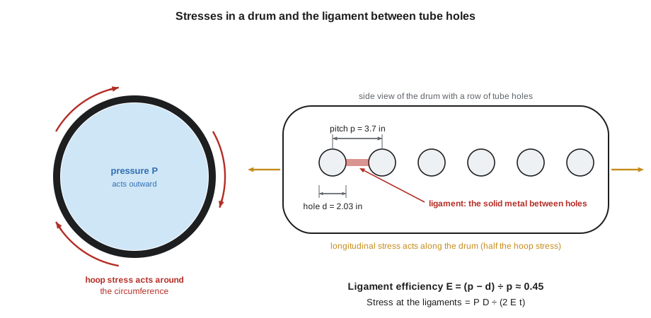
Internal pressure stretches a drum in two directions. The hoop stress, around the circumference, tends to split the drum along its length. The longitudinal stress, along its length, tends to pull the ends off. For a thin cylinder with inside diameter D, wall thickness t and pressure P, PWR-210 lesson 4 gave:
The hoop stress is twice the longitudinal stress, so drums are sized for the hoop stress. Two things in a real drum make it higher than the simple formula suggests:
- Ligaments. The steam drum and mud drum are drilled with rows of holes for the tubes. The strip of metal between two holes, the ligament, is all that carries the stress along that line. The ligament efficiency is the ratio of the ligament width to the hole pitch.
- Joint efficiency. A weld that is not fully examined is given an efficiency less than 1 in the design. Section I drums have fully examined welds, so the tube-hole ligaments usually set the efficiency.
Worked problem
Ligament efficiency
The tube holes along boiler 3's steam drum are 2.03 in in diameter at a pitch of 3.7 in. What is the ligament efficiency?
Show solution
- \[E = \frac{p - d}{p} = \frac{3.7 - 2.03}{3.7} = \frac{1.67}{3.7} \approx 0.45\]
Answer: Only about 45 in 100 of the plate along that line is solid steel, so the drum must be more than twice as thick as a plain cylinder of the same size and pressure.
Including the efficiency E, the hoop stress becomes the formula below. Section I's own drum formula adds small corrections for thicker shells and requires any allowance the designer chooses for corrosion or thinning, but at Cantwell's pressure the simple form gives nearly the same answer.
Worked problem
Required drum thickness
Boiler 3's steam drum has an inside diameter of 42 in and an MAWP of 200 psi. The plate is SA-516 Grade 70 with an allowable stress of about 20,000 psi at the design temperature, and the ligament efficiency is 0.45. The designer added 1/16 in for corrosion. What thickness is needed, and what is the stress in the 9/16 in plate actually used?
Show solution
- Thickness for pressure:
- \[t = \frac{200 \times 42}{2 \times 20{,}000 \times 0.45} = \frac{8{,}400}{18{,}000} \approx 0.467 \text{ in}\]
- Add the corrosion allowance:
- \[0.467 + 0.0625 \approx 0.529 \text{ in}\]
- Stress in the 9/16 in plate (0.5625 in) actually supplied:
- \[\sigma = \frac{200 \times 42}{2 \times 0.45 \times 0.5625} = \frac{8{,}400}{0.506} \approx 16{,}600 \text{ psi}\]
Answer: The plate needs to be at least 0.529 in, and the manufacturer used the next standard size, 9/16 in. At MAWP the ligaments carry about 16,600 psi, under the 20,000 psi allowed. The extra thickness is not spare to be used up: it is the corrosion allowance and the margin the code requires.
This is why the inspector measures drum and tube thickness at internal inspections. If corrosion or pitting has removed more than the allowance, the drum's stress at MAWP is above the allowable value, and the boiler must be repaired or its MAWP reduced.
Thermal stress
Temperature differences cause stress even with no pressure at all. Steel expands about 6.5 millionths of its length for each degree Fahrenheit. If one part of a drum is hotter than another and the cooler part holds it back, the hot part is squeezed and the cold part is stretched. For a part that is completely prevented from expanding, the stress is:
where E_s is the modulus of elasticity of steel, α is the coefficient of expansion and ΔT is the temperature difference that is held back.
Worked problem
Thermal stress from a temperature difference
During a fast warm-up the top of a drum is 90 °F hotter than the bottom. Take E_s = 29,000,000 psi and α = 6.5 × 10⁻⁶ per °F. Estimate the stress if the difference were fully restrained.
Show solution
- \[\sigma = 29{,}000{,}000 \times 6.5 \times 10^{-6} \times 90 \approx 16{,}965 \text{ psi}\]
Answer: About 17,000 psi, almost as much as the pressure stress the drum was designed for. A real drum is only partly restrained, so the actual stress is lower, but the example shows why manufacturers limit warm-up rates and the temperature difference between the top and bottom of a drum.
Thermal stress is highest during start-up, shutdown and sudden changes: firing a cold boiler hard, feeding cold water into a hot drum, or blowing down heavily while firing. Each cycle of stress uses up a little of the metal's fatigue life. Thousands of cycles can start cracks at tube ends, ligaments and nozzles, which is called thermal fatigue (lesson 12). This is also why the feedwater enters through an internal feed pipe that mixes it with hot drum water rather than spraying it onto the shell.
Creep, fatigue and other long-term damage
At high enough temperature, steel under constant stress slowly and permanently stretches, even below its allowable stress at room temperature. This is creep. For carbon steel it becomes important above roughly 750 °F, which is why superheaters and their headers use alloy steels and why their design life is stated in hours of operation. Creep damage builds up silently: the tube swells a little, small voids form along grain boundaries, and eventually the tube ruptures with a thick, fish-mouth split. Running a superheater even a little hotter than its design shortens its life sharply. Cantwell's saturated boilers, at 366 °F, are far below the creep range, but overheating from low water or heavy scale can push tube metal into it within minutes.
- Fatigue: cracking from repeated stress cycles, such as thermal cycling, pressure cycling and vibration.
- Corrosion fatigue: fatigue made worse by corrosion, often at tubes near the drum or where water chemistry is poor.
- Stress corrosion cracking: cracking from stress combined with a specific corrosive agent, such as concentrated caustic (lesson 12).
- Hydrogen damage: hydrogen produced by corrosion under deposits enters the steel and weakens it (lesson 12).
Each of these is controlled by the same three things: good design and materials, good water treatment, and steady operation within the manufacturer's limits. The first is the manufacturer's job; the other two are the operating engineer's.
Grazyna closed the folder. "You will never redesign a drum," she said, "but you will decide how fast to warm one, what water goes into it and when to call the inspector. The numbers in this file are why those decisions matter."
Common mistakes
MistakeThinking the extra plate thickness is spare strength.
InsteadIt is the corrosion allowance and code margin; losing it puts the drum above its allowable stress.
MistakeAssuming any certified welder may repair a boiler.
InsteadThe welder must be qualified to a qualified procedure, under the jurisdiction's registration or certificate rules.
MistakeUsing the plain hoop stress formula for a drilled drum.
InsteadTube-hole ligaments raise the stress; divide by the ligament efficiency.
MistakeTreating thermal stress as minor.
InsteadA restrained temperature difference of 90 °F can produce stress close to the design pressure stress.
MistakeBelieving creep only matters in power stations.
InsteadOverheated tubes in any boiler can enter the creep range in minutes.
Summary and key terms
- The manufacturer's data report records the materials, thicknesses, joints, test pressure and MAWP of every pressure part.
- Boiler materials are named by ASME Section II specifications such as SA-516 plate, SA-178 and SA-192 tubes and SA-106 pipe; allowable stresses fall as temperature rises.
- Section IX groups materials by P-number and qualifies welding through the WPS, PQR and welder performance qualification.
- Drum welds are fully examined, and thick carbon steel parts receive postweld heat treatment.
- Hoop stress, increased by the ligament efficiency of tube holes, sets the drum thickness; corrosion allowance is not spare strength.
- Thermal stress, fatigue and creep explain the limits on warm-up rates, feedwater temperature and tube metal temperature.
- Manufacturer's data report
- The ASME form, signed by the manufacturer and the Authorized Inspector, that records how a boiler was built and tested.
- Allowable stress
- The maximum design stress permitted for a material at a given temperature, listed in ASME Section II Part D.
- P-number
- A Section IX grouping of base metals with similar welding behavior.
- Welding procedure specification
- Written, qualified instructions for making a particular weld.
- Ligament efficiency
- The ratio of solid metal between tube holes to the hole pitch.
- Postweld heat treatment
- Controlled heating and cooling after welding to relieve residual stress and soften hard zones.
- Creep
- Slow, permanent stretching of metal under stress at high temperature.
- Thermal fatigue
- Cracking caused by repeated stresses from temperature changes.
Practice problems
Work each problem on paper first, then reveal the answer to check.
What is the ligament efficiency of tube holes 2 in in diameter at a pitch of 4 in?
Show answer
0.50.
A drum has D = 36 in, MAWP 200 psi, S = 20,000 psi and E = 0.5. What thickness is needed for pressure?
Show answer
0.36 in (7,200 ÷ 20,000).
What does a PQR prove?
Show answer
That a test weld made to the WPS passed the required mechanical tests.
Which P-number covers SA-516 and SA-192?
Show answer
P-No. 1, carbon steel.
Estimate the fully restrained thermal stress for a 54 °F difference with E_s = 29,000,000 psi and α = 6.5 × 10⁻⁶ per °F.
Show answer
About 10,180 psi.
Lesson quiz · 5 questions
Score 60% or more to complete this lesson.
Create a free account to save your progress, take quizzes and earn a certificate.