
IRW-210 · Lesson 6 of 12 · 23 min
Bolted connection types
▶ Video coming soon A video version of this lesson is on the way.
On the Wednesday steel night of October 21, Nate laid three short connections on the yard table, each two plates bolted together, and gave the apprentices a pry bar. "Try to make the plates slide," he said. The first pair, with its bolts snugged by hand and a few turns of a spud wrench, slipped as soon as Jules leaned on the bar, until the bolts came up hard against the sides of their holes. The second pair, with bolts tightened far harder, did not move at all. The third pair had been bolted the same way as the second, but its plates had been painted where they touched, and it slipped. "Three joints, three different ways of carrying load," Nate said. "The drawing tells you which one you are building. You have to build the one it says."
This lesson explains how bolted joints carry load, the difference between snug-tight, pretensioned and slip-critical joints, what thread conditions and faying surfaces mean, and the common types of bolted connection an ironworker meets on a building frame.
How a bolt carries load
Most bolts in a building frame are loaded in shear: the plates they join try to slide past each other, and the bolt shank resists by bearing against the sides of the holes and being cut across, like a pin through two pieces of wood. A bolt that joins two plates is in single shear, cut on one plane; a bolt that joins a plate between two other plates is in double shear, cut on two planes, and can carry about twice the load. Some bolts are loaded in tension, pulled along their length, for example in hangers and in end-plate connections where a beam tries to pull away from a column. Many bolts see a little of both.
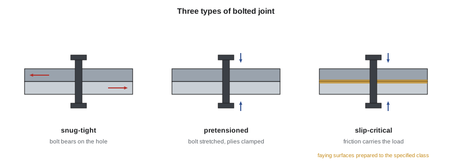
When a bolt is tightened hard, it stretches like a stiff spring and clamps the plates together. That clamping force, called pretension, does two useful things. It squeezes the plates so tightly that friction between them carries load without the plates sliding at all. And it keeps the nut from loosening under vibration or reversing loads. Whether a joint relies on that clamping force is what separates the three types of joint.
The three types of joint
- Snug-tight joint. The bolts are brought to the snug-tight condition: the plies are in firm contact, achieved by the full effort of an ironworker with an ordinary spud wrench or a few impacts of an impact wrench. Load is carried by the bolts bearing against the holes. Most simple beam shear connections in buildings are snug-tight, because they carry steady gravity loads and a little slip into bearing does no harm.
- Pretensioned joint. The bolts are tightened to a specified minimum pretension, using one of the approved methods (lesson 7). Load is still designed to be carried in bearing, but the pretension is needed for other reasons: vibration, fatigue, load reversal, or connections the designer wants to keep tight, such as some brace connections and column splices.
- Slip-critical joint. The bolts are pretensioned and the faying surfaces are prepared to a specified class, so that the joint carries its load by friction and does not slip at all. Used where slip would cause problems: oversized or slotted holes in the direction of load, connections that see load reversal, and bracing where any slip would let the frame move.
From the outside, the three joints can look identical. The difference is in how the bolts were tightened and how the surfaces were prepared, which is why the drawings mark each connection type and why the inspector (lesson 8) checks the process as much as the result.
How the drawings show joint type
The general notes and the connection details say which joints are which. Common ways of marking them are the letters ST, PT and SC beside a bolt group, or a note such as "all connections snug-tight unless noted" with exceptions marked. The bolt callout also gives the diameter, the grade, and sometimes the thread condition and the hole type.
Thread condition matters because a bolt is weaker where its threads cross the shear plane than where its full shank does. A bolt with threads included in the shear plane is marked N; one with threads excluded is marked X. If a connection is designed as X, the bolt must be long enough, and the grip arranged, so that the threads sit outside the plies. Using a shorter bolt, or putting the nut on the wrong side, can put threads into the shear plane and cut the joint's strength.
Hole type matters too. Standard holes are slightly larger than the bolt. Oversized holes and short- or long-slotted holes allow more adjustment, but they make bearing less reliable, so they often need hardened washers or plate washers and may require the joint to be slip-critical. The drawings show where these holes are used, and the field does not create them by reaming or slotting without approval.
Worked problem
Shear planes in a double-angle connection
A beam is connected to a column with two clip angles, one on each side of the beam web. Three bolts pass through the angles and the beam web, and three more pass through the angles and the column flange. How many shear planes does each bolt through the beam web have, and each bolt through the column flange?
Show solution
- Bolts through the beam web pass through angle, web, angle: two interfaces, so two shear planes (double shear).
- Bolts through the column flange pass through one angle and the flange: one interface, so one shear plane (single shear).
Answer: Two shear planes for the web bolts and one for the flange bolts, which is one reason the designer can use the same number of bolts on each leg even though the flange bolts do less work each. The ironworker does not do the design, but knowing it explains why bolts are placed where they are.
Worked problem
The area of a bolt
What is the area of the shank of a 3/4 in bolt in square inches?
Show solution
- Area = π × d² ÷ 4.
- Area = 3.1416 × 0.75² ÷ 4 = 0.442 in².
Answer: About 0.442 in². The area of steel through the threads is smaller, which is why threads in the shear plane reduce a bolt's strength.
Faying surfaces in slip-critical joints
The friction that holds a slip-critical joint depends on the condition of the faying surfaces, the surfaces of the plies in contact. The specifications classify surfaces by their slip coefficient: Class A surfaces, such as clean mill scale or certain approved coatings, and Class B surfaces, such as blast-cleaned steel or approved coatings with a higher coefficient. The designer chooses the class, and the fabricator prepares the surfaces in the shop, usually leaving them unpainted or applying a qualified coating, and masking them from the general paint.
In the field, the faying surfaces must stay as the shop left them. Paint overspray, grease, oil, loose rust, dirt, ice or a stray coat of primer can ruin the slip resistance. Nate's rule is to look at every faying surface before the plies go together, and to stop and report any surface that has been painted or contaminated. Wire-brushing paint off a surface is not a fix unless the engineer says so, because it does not restore the specified class.
Common bolted connections in a building
- Double-angle connections. Two clip angles on the beam web, bolted or welded to the beam and bolted to the support. The traditional simple shear connection.
- Shear tabs, also called single plates or fin plates. A single plate welded to the column or girder in the shop, with the beam web bolted to it. Quick to connect, because the connector only has to land the web against the plate.
- Seated connections. A seat angle or stiffened seat on the support carries the beam's reaction, and a top angle holds it in place. Useful where the beam has to be lowered in between other steel.
- End-plate connections. A plate welded to the end of the beam and bolted to the column flange. Some are simple shear connections; others, with more bolts and thicker plates, are moment connections that resist bending.
- Brace connections. Gusset plates at beam and column intersections, with the brace bolted to the gusset. Often pretensioned or slip-critical.
- Splices. Plates bolted across the joint between two lengths of beam or column.
At Ashcroft, the floor beams had shear tabs and were snug-tight; the braces in the middle bays were slip-critical with twist-off bolts; and the moment frames at the ends had bolted end plates that were pretensioned. Each type had its own detail on the erection drawings and its own line in the bolting procedure Nate kept in the gang box.
Bolt assemblies
A structural bolt assembly is the bolt, the nut and, where required, one or more washers, made and supplied together. The nut and washer must be the grade and type the bolt standard calls for. Mixing a structural bolt with a hardware-store nut, or with a nut from a different lot, can lead to stripped threads or a bolt that never reaches its pretension. On pretensioned and slip-critical work, assemblies are kept together by lot from the supplier to the connection, which is why bolts arrive in kegs or boxes marked with a lot number and why the inspector asks to see them (lessons 7 and 8).
Washers
Washers have specific jobs in high-strength bolting, and the drawings and the bolting specification say where they go. Hardened washers to ASTM F436 are used under the element being turned when the calibrated wrench method is used, under twist-off bolts as their makers require, over oversized and slotted holes in outer plies, and where the specification calls for them. Plate washers or thick bar washers cover long slots in outer plies. Beveled washers are used where the surface under the head or nut slopes more than the specification allows, as on the sloped flanges of channels and S shapes. In a snug-tight joint with standard holes, washers are often not needed at all. Putting washers where they are not required does little harm; leaving them out where they are required can let the bolt head dig into the plate and lose tension.
Bolt length and stick-through
The length of a bolt is chosen for the grip, the total thickness of the plies, plus the washers, the nut and a little extra. The specifications require the end of the bolt to be at least flush with the outer face of the nut. Too short, and the nut does not engage all its threads; too long, and the nut may run out of thread before it reaches the plies, so that the bolt seems tight but does not clamp them. Detailers choose the length, and the bolt list for each connection says what it is. In the field, the bolt-up crew checks each bolt's stick-through as it goes, and a bolt that is too short or that "bottoms out" on its threads is replaced with the right length, not forced.
Why the designer chose the joint type
Knowing why a joint was designed the way it was helps the crew build it right. A beam shear connection is usually snug-tight because it carries a steady gravity load and a little slip does no harm. A brace in a braced frame is often slip-critical because it carries wind loads that reverse direction, and any slip would let the building sway back and forth a little with each gust, loosening the joint over time. A column splice may be pretensioned to keep it tight under vibration. When the crew understands this, it is less tempted to treat a slip-critical joint as just another set of bolts.
Joints that combine bolts and welds
Some connections are bolted on one side and welded on the other, such as a shear tab welded to a column in the shop and bolted to the beam in the field. A few combine bolts and welds in the same joint to carry the same load, which is unusual and is designed carefully, because bolts in bearing and welds share load differently. The field rule is simple: build each joint exactly as detailed, and do not add field welds to a bolted connection, or bolts to a welded one, to make up for a problem. Any field welding not shown on the drawings needs the engineer's approval and a qualified welder, as IRW-310 explains.
Common mistakes
MistakeAssuming every joint is snug-tight because most are.
InsteadRead the joint type for each connection on the drawings.
MistakeUsing a shorter bolt so the nut fits better.
InsteadUse the specified length; a short bolt can put threads in the shear plane.
MistakePainting or wire-brushing faying surfaces on a slip-critical joint.
InsteadKeep faying surfaces as the shop prepared them; report any contamination.
MistakeReaming or slotting a hole to make a joint fit.
InsteadOversized and slotted holes change the design; they need the engineer's approval.
MistakeMixing bolts, nuts and washers from different lots.
InsteadKeep assemblies together by lot.
Summary and key terms
- Bolts usually work in shear, bearing on their holes; some work in tension.
- Snug-tight joints are brought to firm contact; pretensioned joints have bolts tightened to a minimum pretension; slip-critical joints carry load by friction.
- The drawings mark each joint ST, PT or SC, with bolt grade, size, thread condition and hole type.
- Threads in the shear plane reduce bolt strength; condition X keeps them out.
- Slip-critical faying surfaces must stay clean and as prepared.
- Bolt, nut and washer are an assembly, kept together by lot.
- Snug-tight
- Plies in firm contact, reached by the full effort of an ironworker with a spud wrench or a few impacts of an impact wrench.
- Pretension
- The clamping force in a tightened bolt.
- Slip-critical joint
- A joint designed to carry load by friction without slipping.
- Single shear
- A bolt cut on one plane.
- Double shear
- A bolt cut on two planes, carrying about twice the load of single shear.
- Thread condition
- Whether the threads are included (N) or excluded (X) from the shear plane.
- Shear tab
- A single plate welded to a support, to which a beam web is bolted.
- Bolt assembly
- A bolt, nut and washers made and supplied to work together.
Practice problems
Work each problem on paper first, then reveal the answer to check.
What does SC beside a bolt group mean?
Show answer
Slip-critical.
A bolt passes through a plate between two other plates. Single or double shear?
Show answer
Double shear.
What is the shank area of a 7/8 in bolt?
Show answer
3.1416 × 0.875² ÷ 4 ≈ 0.601 in².
A slip-critical faying surface has paint overspray. What do you do?
Show answer
Stop and report it.
Why keep bolt assemblies together by lot?
Show answer
So the bolt, nut and washer work together and can be traced and tested.
Lesson quiz · 5 questions
Score 60% or more to complete this lesson.
Create a free account to save your progress, take quizzes and earn a certificate.