
INS-410 · Lesson 5 of 12 · 24 min
Thickness to prevent condensation
▶ Video coming soon A video version of this lesson is on the way.
Marcel Ouellet's Monday evening sessions in INS-320 taught Devon, Tessa and Priya how to read a hygrometer, find a dew point and check whether a cold surface would sweat. At the end of the last session, Marcel told them that the full thickness calculation would come later, "when Raj gets hold of you". Raj's chance came with an item near the end of Thea Okerlund's audit: Kellerton's budget for 2027 includes replacing a run of the low-temperature ammonia suction main in the engine room, and Anika Varga wanted to know what thickness the new insulation would need. "For cold work, energy is almost never the question," Raj said. "The question is whether water forms on the outside. Get that wrong and nothing else matters."
This lesson develops the condensation control calculation: the design conditions to use, the dew point and the margin, how to find the surface temperature of a cold insulated pipe, and how to choose the thickness that keeps it dry. It shows why a shiny jacket needs more insulation on cold work, and why thickness alone never stops moisture getting into the insulation.
What the calculation must prevent
Water forms on any surface colder than the dew point of the air around it. On an insulated cold pipe there are two places it can happen. The first is the outside of the jacket: if the jacket is below the dew point, it sweats, drips and stains the ceiling or floor, and wet jackets corrode. The thickness calculation prevents this. The second is inside the insulation, where water vapor driven in by the vapor pressure difference condenses and freezes as it nears the cold pipe, as INS-320 explained. Thickness does not prevent that; only a continuous, sealed vapor retarder does. Both must be right.
The calculation therefore answers one question: what thickness keeps the outer surface at or above the dew point, plus a margin, at the design conditions?
Design conditions and margin
The design conditions are the air temperature and relative humidity the surface must tolerate, usually the worst combination expected in the space. They come from the specification, or from the owner and engineer for plant work. Typical choices are:
| Location | Typical design condition |
|---|---|
| Conditioned office ceiling space | 75 °F, 50 in 100 relative humidity |
| Mechanical room, unconditioned | 80 to 90 °F, 60 to 80 in 100 |
| Refrigeration engine room in summer | 86 to 90 °F, 70 to 80 in 100 |
| Outdoors in a humid summer climate | local design data; often 80 to 90 in 100 at a moderate temperature |
| Washdown or food processing area | up to 90 in 100 or more |
Because humidity varies and instruments and insulation are not perfect, calculations add a margin: the surface must be some degrees above the dew point, not just at it. INS-320 used 4 °F for Carrow Park, a common choice. Some specifications use more.
Kellerton's engine room design condition, from Anika, is 90 °F and 70 in 100 relative humidity, the worst summer afternoon with the doors closed and the compressors running.
Worked problem
Dew point by the Magnus formula
Find the dew point of air at 90 °F and 70 in 100 relative humidity. Convert to Celsius, use the Magnus formula from INS-320 with constants 17.62 and 243.12 °C, and convert back.
Show solution
- T = (90 − 32) ÷ 1.8 = 32.2 °C.
- γ = ln 0.70 + 17.62 × 32.2 ÷ 275.34 = −0.3567 + 2.0619 = 1.7052.
- Dew point = 243.12 × 1.7052 ÷ (17.62 − 1.7052) = 26.05 °C = 78.9 °F.
- Required surface temperature with a 4 °F margin: 78.9 + 4 = 82.9 °F.
Answer: The jacket must stay at or above about 82.9 °F.
A moist room leaves very little room: at 70 in 100 relative humidity, the dew point is only about 11 °F below the air temperature, and the margin takes a third of that. In a drier room the job is much easier.
The surface temperature of a cold pipe
The calculation is the same as for a hot pipe, from lesson 2, with the heat flowing inward. The heat gain per unit length is still (Tₚ − Tₐ) ÷ (Rᵢₙₛ + Rₛ), which comes out negative because the pipe is colder than the air, and the surface temperature is still Tₛ = Tₐ + q Rₛ, which comes out below the air temperature. Two differences from hot work matter:
- The temperature difference across the surface film is small, only a few degrees, so convection is weak and radiation, which depends on emittance, carries most of the heat. That makes the jacket choice even more important than on hot work.
- The conductivity is taken at a low mean temperature, often below freezing, where most insulations conduct less than at room temperature. Data sheets list values at low mean temperatures for cold-service materials such as cellular glass, polyisocyanurate and elastomeric foam.
Worked problem
The ammonia suction main
The new suction main is 6 in (outside diameter 6.625 in) carrying ammonia at −30 °F. Raj tries 2 in of polyisocyanurate, typical k = 0.17 Btu·in/h·ft²·°F at its mean temperature, with a PVC jacket (emittance 0.90), in air at 90 °F. Find the surface temperature and check it against the 82.9 °F required.
Show solution
- Radii: r₁ = 3.3125 in, r₂ = 5.3125 in; D₂ = 0.885 ft.
- Rᵢₙₛ = ln(5.3125 ÷ 3.3125) ÷ (2π × 0.17 ÷ 12) = 0.4724 ÷ 0.0890 = 5.307 h·ft·°F/Btu.
- Iteration 1: guess Tₛ = 82 °F. hc = 0.468, hr = 1.003, h = 1.471 Btu/h·ft²·°F; Rₛ = 1 ÷ (1.471 × π × 0.885) = 0.244.
- q = (−30 − 90) ÷ (5.307 + 0.244) = −120 ÷ 5.551 = −21.6 Btu/h·ft (a heat gain of 21.6 Btu/h·ft).
- Tₛ = 90 + (−21.6 × 0.244) = 84.7 °F.
- Iteration 2: h = 1.434, Rₛ = 0.251, q = −21.6, Tₛ = 84.6 °F. Check: 84.6 °F is above the 82.9 °F required.
Answer: 2 in of polyisocyanurate with a PVC jacket passes at the design condition, with a little margin to spare.
Look at how much of the surface coefficient is radiation: 1.00 of 1.47. On a cold surface only a few degrees below the air, convection is weak, and the surroundings, the walls, ceiling and other equipment, warm the jacket by radiation. That is why the emittance matters so much.
Choosing the thickness, and the jacket
Repeating the calculation for each standard thickness, with both kinds of jacket, gives the full picture:
| Thickness | PVC jacket (ε = 0.90) | Aluminum jacket (ε = 0.10) |
|---|---|---|
| 1 in | 79.3 °F (fails) | 69.6 °F (fails) |
| 1 ½ in | 82.8 °F (fails) | 75.2 °F (fails) |
| 2 in | 84.6 °F (passes) | 78.3 °F (fails) |
| 2 ½ in | 85.7 °F | 80.3 °F (fails) |
| 3 in | 86.5 °F | 81.7 °F (fails) |
| 3 ½ in | 87.0 °F | 82.8 °F (fails) |
| 4 in | 87.4 °F | 83.6 °F (passes) |
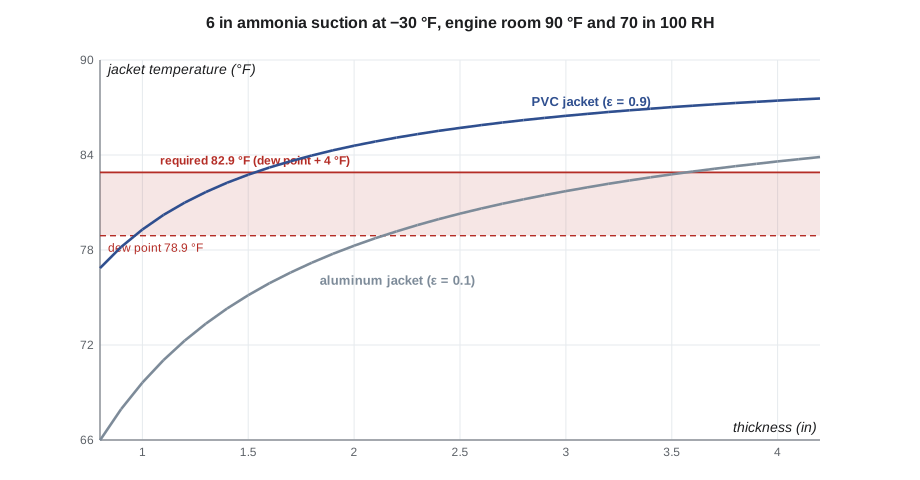
The answer surprised Priya: with an aluminum jacket, the same main needs 4 in of insulation, more than twice the PVC thickness. The reason is the one above. The aluminum jacket receives less radiant heat from the warm room, so it runs colder. On hot work a shiny jacket gives a hotter surface; on cold work it gives a colder one, and in both cases that is the wrong direction.
Engine rooms often use aluminum jackets anyway, for their durability and fire performance, so the design must use the thicker insulation or an aluminum jacket with a painted or high-emittance finish, which behaves more like PVC. Raj noted both options for Anika and recommended the thicker system with aluminum, matching the rest of Kellerton's engine room, because the ammonia lines are struck by forklifts and cleaned with hoses. INS-320's Carrow Park plant room used 3 in of cellular glass with aluminum jacket, at a milder design condition of 86 °F and 50 in 100.
Heat gain and energy on cold work
Condensation usually governs cold work, but the heat gain still costs money: every watt that leaks into a refrigerated line must be removed by the refrigeration system, which uses electricity to do it. At low temperatures the system's coefficient of performance (COP), the heat removed per unit of electricity, is low; INS-320 used about 1.8 at −30 °F.
Worked problem
The cost of the heat gain
A 100 ft run of the suction main with 2 in of polyisocyanurate gains 21.6 Btu/h·ft. The system runs 7,550 hours a year with a COP of 1.8. About how much electricity does the heat gain cost each year?
Show solution
- Heat gain: 21.6 × 100 = 2,160 Btu/h = 2,160 ÷ 3,412 = 0.633 kW.
- Electricity: 0.633 ÷ 1.8 = 0.352 kW, running 7,550 h: 0.352 × 7,550 = 2,660 kWh a year.
Answer: About 2,660 kWh a year: small for one run, but cold systems in a large plant add up, and wet insulation can multiply the gain several times.
Thickness is not enough
A condensation calculation assumes dry insulation. If the vapor retarder is broken, vapor moves into the insulation, condenses, freezes and keeps building, and the wet insulation conducts heat many times better than dry. The surface temperature then falls, the jacket sweats in spite of the correct thickness, and the problem gets worse every season. INS-110's iced suction line at Kellerton and INS-320's resurfacer room line at Carrow Park were both failures of the vapor retarder, not of thickness. Every cold system therefore needs:
- A low-permeance vapor retarder, continuous and sealed at every joint, as INS-320 described.
- Vapor stops at intervals and at every fitting, so that damage stays local.
- Sealed penetrations at hangers, supports and through walls, with high-density inserts that keep the retarder continuous.
On cold work, the calculation sets the thickness, and the workmanship sets whether that thickness works.
A chilled water example
Chilled water is the most common cold system in commercial buildings, and it shows how strongly the design condition decides the thickness. Take an 2 in chilled water line at 43 °F with flexible elastomeric insulation, typical k = 0.25 Btu·in/h·ft²·°F, and a high-emittance surface:
| Space | Dew point | Required surface (margin 4 °F) | ½ in | ¾ in | 1 in |
|---|---|---|---|---|---|
| Office ceiling, 75 °F and 50 in 100 | 55.1 °F | 59.1 °F | 68.1 °F (passes) | 70.1 °F | 71.3 °F |
| Mechanical room, 81 °F and 70 in 100 | 70.3 °F | 74.3 °F | 73.0 °F (fails) | 75.4 °F (passes) | 76.7 °F |
In the office ceiling, even the thinnest size keeps the surface dry. In a humid mechanical room, like the Mountview penthouse design condition of 81 °F and 70 in 100 in INS-210, the thinnest size fails and the next one passes. In both spaces the energy code usually requires more than either, so for chilled water in buildings the code often governs, and the condensation check confirms that the code thickness is enough.
When the design condition is wrong
A condensation calculation is only as good as its design condition. Common causes of sweating on correctly insulated lines are spaces that turned out more humid than designed: a mechanical room where the ventilation was never balanced, a ceiling above a kitchen or shower room, a plant room with an open door in a summer storm. When a cold system sweats, check the room conditions with a hygrometer before blaming the insulation, as Marcel taught in INS-320; if the room is wetter than the design, the owner needs to know, because more insulation may only move the problem.
Below-ambient work and the jacket over time
Emittance is not fixed for the life of a system. A new aluminum jacket may start near 0.05 and, as it dulls, weathers and collects dust, rise toward 0.2 or more; PVC and painted jackets stay high. On cold work this means a shiny jacket is at its worst when new, which is exactly when the system is commissioned and inspected, so the design should use the new-jacket value, not an aged one.
Common mistakes
MistakeUsing average conditions for the room.
InsteadUse the worst expected combination of temperature and humidity.
MistakeDesigning to the dew point with no margin.
InsteadAdd a margin, commonly 4 °F or as the specification states.
MistakeAssuming a shiny jacket helps on cold work.
InsteadA low-emittance jacket runs colder and needs more thickness; calculate with its emittance.
MistakeUsing a room-temperature conductivity for a cold line.
InsteadUse the conductivity at the low mean temperature.
MistakeRelying on thickness to keep insulation dry.
InsteadThickness stops surface sweating; only a continuous, sealed vapor retarder keeps the insulation dry.
Summary and key terms
- Condensation control keeps the jacket at or above the dew point plus a margin at the worst design conditions.
- The dew point comes from the Magnus formula or a psychrometric chart; at high humidity it is only a few degrees below the air temperature.
- The cold pipe calculation is the same as the hot one, with heat flowing inward; radiation carries most of the surface heat transfer.
- On the Kellerton suction main, 2 in with a PVC jacket passes, but an aluminum jacket needs 4 in.
- Heat gain costs electricity at a low COP, and only a sealed vapor retarder keeps the insulation dry enough for the calculation to hold.
- Design condition
- The air temperature and relative humidity a cold surface must tolerate, usually the worst expected.
- Dew point
- The temperature at which water vapor in the air begins to condense on a surface.
- Margin
- The number of degrees by which the surface must exceed the dew point in a condensation calculation.
- Heat gain
- Heat flowing into a cold pipe or vessel from its surroundings.
- Coefficient of performance
- The heat a refrigeration system removes for each unit of energy it uses.
- Condensation control
- Insulation designed to keep a cold surface above the dew point.
Practice problems
Work each problem on paper first, then reveal the answer to check.
What is the dew point of air at 90 °F and 70 in 100 relative humidity?
Show answer
About 78.9 °F.
With a 4 °F margin, what surface temperature is required?
Show answer
About 82.9 °F.
Why does the aluminum-jacketed main need more insulation than the PVC one?
Show answer
The aluminum receives less radiant heat from the room, so it runs colder.
What carries most of the heat to the outside of a cold jacket?
Show answer
Radiation from the warmer surroundings.
What prevents water getting into the insulation itself?
Show answer
A continuous, sealed vapor retarder with vapor stops and sealed penetrations.
Lesson quiz · 5 questions
Score 60% or more to complete this lesson.
Create a free account to save your progress, take quizzes and earn a certificate.