
INS-410 · Lesson 6 of 12 · 22 min
Freeze protection and heat tracing
▶ Video coming soon A video version of this lesson is on the way.
Thea Okerlund's audit was mostly about steam, but one outdoor item caught Raj's eye. Kellerton's 2 in make-up water line runs about 100 ft along the yard rack to the boiler house. It is electrically heat traced and insulated, and her thermal images taken on a cool September morning showed two warm bands along it where the jacket had been opened for a valve repair and closed badly. "Wet insulation on a traced line is the worst of both," Raj said. "The tracing runs all winter trying to heat the rain, and the day the power trips, the pipe freezes faster than anyone expects."
This lesson explains how insulation delays freezing but cannot prevent it in still water, how to estimate the time a line takes to start freezing and to freeze partly, how heat tracing is sized to hold a line above freezing, and what the insulator must do so that a traced system works.
What insulation can and cannot do
Water in a pipe freezes when the heat it loses has removed both its sensible heat, the heat given up as it cools to 32 °F, and its latent heat of fusion, the much larger amount given up as it turns to ice. Insulation slows the rate of heat loss, but it does not add any heat. In water that is not flowing, and with the air below freezing long enough, the water will freeze sooner or later whatever the thickness. Insulation therefore buys time: enough, if the calculation is right, to cover a short shutdown or a cold night with no flow. Where the line must never freeze, heat must be added, by keeping the water flowing, by draining the line, or by heat tracing.
Two practical points follow. First, flowing water seldom freezes, because it keeps bringing heat; the risk is when flow stops. Second, a line that is drained when not in use needs no freeze calculation at all, which is why many plants drain seasonal outdoor lines.
Time to start freezing and to freeze
A simple estimate treats the water and the pipe metal as one lump of stored heat cooling through the insulation. The heat loss per unit length at any water temperature T is UA × (T − Tₐ), where UA is the overall conductance per unit length, 1 ÷ (Rᵢₙₛ + Rₛ). The cooling follows an exponential curve with a time constant τ:
where m c is the heat capacity of the water and pipe per unit length. The time to cool from the starting temperature Tᵢ to freezing is then:
where T_f is the freezing point. Once the water reaches 32 °F, its temperature stays there while ice forms, and the time to freeze a fraction f of the water is the latent heat divided by the heat loss at the freezing point:
where m_w is the mass of water per unit length and L_f is the latent heat of fusion, about 144 Btu/lb. Design guides often use the time to freeze a quarter of the water as the limit, because a pipe can usually tolerate some ice in the middle but not a full plug.
Worked problem
The make-up water line with no flow
The make-up line is 2 in Schedule 40 steel (outside diameter 2.375 in, inside diameter 2.067 in, 3.65 lb/ft of steel), insulated with 2 in of mineral wool, typical k = 0.25 Btu·in/h·ft²·°F near 32 °F, with an aluminum jacket. In wind, use a surface coefficient of about 3.5 Btu/h·ft²·°F. The water starts at 50 °F and the air is at the plant's design minimum of −13 °F. Estimate the time to reach 32 °F and the time to freeze a quarter of the water, with no flow and no tracing.
Show solution
- Water per foot: π ÷ 4 × (2.067 ÷ 12)² × 62.4 = 1.454 lb.
- Heat capacity: 1.454 × 1.0 + 3.65 × 0.11 = 1.454 + 0.402 = 1.856 Btu/°F per foot.
- Rᵢₙₛ = ln(3.1875 ÷ 1.1875) ÷ (2π × 0.25 ÷ 12) = 0.987 ÷ 0.1309 = 7.543; Rₛ = 1 ÷ (3.52 × π × 0.531) = 0.170 h·ft·°F/Btu.
- UA = 1 ÷ (7.543 + 0.170) = 0.1296 Btu/h·ft·°F.
- τ = 1.856 ÷ 0.1296 = 14.3 h.
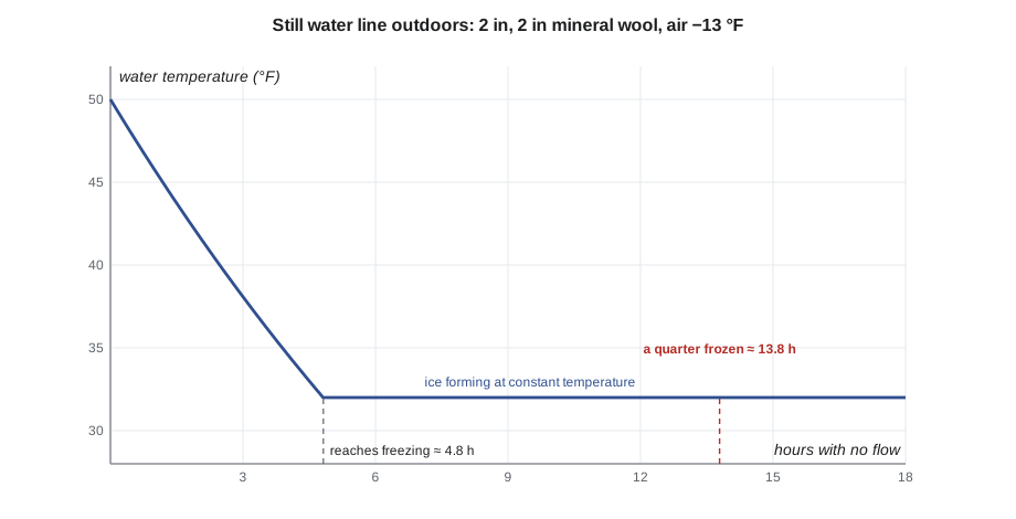
- t_cool = 14.3 × ln(63 ÷ 45) = 14.3 × 0.336 = 4.8 h.
- Heat loss at 32 °F: 0.1296 × 45 = 5.83 Btu/h·ft.
- t_freeze (a quarter) = 0.25 × 1.454 × 144 ÷ 5.83 = 9.0 h.
- Total: about 4.8 + 9.0 = 13.8 h.
Answer: With dry insulation, the still line would start to freeze after about 5 hours and be a quarter frozen after about 14. That is enough to ride through a short power cut, but not a weekend shutdown in a cold snap.
The estimate is simple and slightly optimistic: it ignores that water near the wall freezes first, that valves, flanges and supports lose heat faster than straight pipe, and that a small line freezes far faster than a large one. A line of 1 in or smaller can freeze in a fraction of the time, and wet insulation, with several times the conductivity, can cut the time by more than half. Freeze times are used to judge risk, not to promise safety.
Sizing heat tracing
Heat tracing replaces the heat the line loses, so that it never cools below a chosen maintain temperature, usually about 40 °F for freeze protection. The heat it must supply per unit length is simply the heat loss at the maintain temperature and the lowest design ambient:
where SF is a safety factor, commonly about 1.1 to 1.25 in design guides, to allow for insulation in less than perfect condition, voltage variation and fittings. The electrical engineer or the tracing supplier makes the design, but the insulator should understand it, because the insulation is half of the system: halve the conductance and you halve the tracing.
Worked problem
Sizing tracing for the make-up line
Using UA = 0.1296 Btu/h·ft·°F from the previous example, a maintain temperature of 41 °F, the −13 °F design minimum and a safety factor of 1.2, what output per foot is needed? Self-regulating cables are sold in nominal outputs of about 3, 5, 8 and 10 W/ft.
Show solution
- Heat loss at the maintain temperature: 0.1296 × (41 − (−13)) = 0.1296 × 54 = 7.00 Btu/h·ft.
- In watts: 7.00 ÷ 3.412 = 2.05 W/ft. With safety factor: 2.05 × 1.2 = 2.46 W/ft.
- Choose the next cable output up: 3 W/ft.
Answer: A 3 W/ft cable on dry insulation does the job. On the same line with wet insulation at several times the conductivity, it would not.
Cable length is more than the pipe length. Valves, flanges, pumps and pipe supports each need extra cable, looped or spiralled on, to make up for their extra heat loss, and the supplier's design guide gives allowances. On the make-up line, with typical allowances of about 4 ft per valve, 1 ft per support and 3 ft for the ends:
| Item | Allowance |
|---|---|
| Pipe | 100 ft |
| 2 valves × 4 ft | 8 ft |
| 6 supports × 1 ft | 6 ft |
| Power connection and end seal | 3 ft |
| Total | 117 ft |
At 3 W/ft × 117 ft = 351 W, the circuit draws about 350 W at full output. With an ambient-sensing controller that turns it on only below about 40 °F, it might run some 2,500 hours a year, about 880 kWh. If the insulation is wet, it runs more, at full output, and may still fail to hold the line on the coldest night.
Kinds of heat tracing
| Type | How it works | Typical use |
|---|---|---|
| Self-regulating cable | A conductive polymer core whose output falls as its temperature rises, so it gives more heat where the pipe is colder | Freeze protection and low-temperature process maintenance; cannot overheat itself; can be overlapped |
| Constant wattage cable | A fixed output per length, controlled by a thermostat | Long runs and higher temperatures; must not overlap; needs control |
| Mineral-insulated (MI) cable | A metal-sheathed cable with mineral insulation | High temperatures and high outputs, such as process lines |
| Steam tracing | A small steam tube run alongside the pipe | Plants with steam available, heavy oils and process lines |
Standards govern the products and their installation. In both countries, heat tracing products are tested and certified to their electrical standards, such as the IEEE and IEC trace heating standards (IEEE 515 has been replaced by the joint IEC/IEEE 62395-1:2024), and the electrical code covers the circuit. Article 427 of the NEC deals with fixed heating of pipelines, and both codes call for ground-fault protection on most pipe tracing circuits. The electrical work is done by a licensed electrician; the insulator installs the insulation over it.
The insulator's part
A heat traced line works only if its insulation is dry, complete and the right size, and the insulator is the one who makes it so. The usual practices are:
- Check before covering. The electrician tests the cable's insulation resistance before the insulation goes on and again after; do not insulate a section that has not been tested, and report any damage at once.
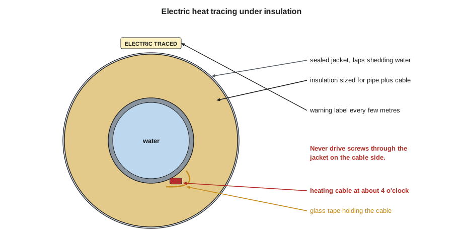
- Size the insulation for pipe plus cable. Use the next pipe size of insulation up, or a size made for traced pipe, so the cable is not crushed and there is no gap; the specification or the supplier says which.
- Keep the cable where it was placed, usually on the lower part of the pipe at the 4 or 8 o'clock position on horizontal runs, where it is protected and heats the cold bottom of the pipe.
- Never drive screws or rivets through the jacket where the cable runs. Fasten jackets with bands, or keep screws well away from the cable side, and mark the jacket.
- Seal every cable entry and exit through the jacket, and seal the jacket against weather, because wet insulation is the commonest cause of traced lines freezing.
- Label the jacket "electric traced" at regular intervals, typically every 10 ft and at every valve, so that others know before they cut.
- Use aluminum tape over the cable on plastic pipe, if the supplier calls for it, to spread the heat.
On the make-up line, Raj's price included removing the wet sections, drying and testing, new insulation sized for the traced pipe, a sealed jacket and new labels, with Kellerton's electrician testing the cable before and after. The work is planned for the spring, when the line can be drained and the tracing turned off (a plan).
Other ways to keep water from freezing
Heat tracing is not the only answer, and on many plants it is not the first. Lines that can be drained in winter, such as summer cooling water or outdoor wash stations, are often simply valved off and drained, with a low-point drain and a high-point vent. Lines that must stay in service can be kept flowing: a small continuous bleed or a recirculation loop keeps warm water moving, at the cost of the water or pumping energy. Where steam is available, a steam tracer does the same job as an electric one. The insulator's work on all of these is the same: dry, complete, well-sealed insulation, because every method depends on slowing the heat loss.
Process temperature maintenance
Heat tracing is also used to hold process lines at a working temperature, to keep heavy oils, sugar solutions, chocolate or chemicals fluid, rather than just above freezing. The sizing method is the same, with the maintain temperature set by the process, often 100 to 300 °F, and the cable chosen for that temperature range. These systems usually need closer temperature control and more careful insulation, because a cold spot at a support or valve can let the product set in the pipe, and because the operating cost of the tracing runs all year rather than only on cold nights.
Common mistakes
MistakePromising that insulation prevents freezing.
InsteadInsulation only delays freezing in still water; heat, flow or draining prevents it.
MistakeCalculating the time to freeze for a large line and applying it to small branches.
InsteadSmall lines freeze far faster; check them separately.
MistakeSizing tracing for dry insulation and then leaving the jacket open.
InsteadSeal the jacket; wet insulation multiplies the heat loss and defeats the tracing.
MistakeCrushing the cable by using pipe-size insulation.
InsteadUse insulation sized for pipe plus cable as the specification or supplier directs.
MistakeScrewing a jacket through a heating cable.
InsteadUse bands or keep fasteners away from the cable side, and mark the jacket.
Summary and key terms
- Insulation delays freezing but cannot prevent it in still water below freezing; heat, flow or draining prevents it.
- Time to reach freezing is τ ln((Tᵢ − Tₐ) ÷ (T_f − Tₐ)) with τ = m c ÷ UA; time to freeze a fraction is f m_w L_f ÷ (UA (T_f − Tₐ)).
- The make-up line takes about 5 hours to reach freezing and about 14 hours to freeze a quarter, at the design minimum with dry insulation.
- Heat tracing output is the heat loss at the maintain temperature and lowest ambient, times a safety factor; the make-up line needs a 3 W/ft cable.
- Insulators keep traced insulation dry, correctly sized, sealed and labeled, and never fasten through the cable.
- Sensible heat
- Heat that changes a substance's temperature.
- Latent heat of fusion
- The heat released when water freezes or absorbed when ice melts, about 144 Btu/lb.
- Time constant
- The heat capacity divided by the conductance; it sets how fast an insulated line cools.
- Heat tracing
- An electric cable or steam tube that adds heat to a pipe to keep it above a set temperature.
- Maintain temperature
- The temperature heat tracing is designed to hold.
- Self-regulating cable
- Heat tracing whose output falls as its temperature rises.
- Safety factor
- A multiplier on the calculated heat loss to allow for imperfect conditions.
Practice problems
Work each problem on paper first, then reveal the answer to check.
Why can insulation not prevent freezing in a still pipe?
Show answer
It slows heat loss but adds no heat, so in time the water loses its heat and freezes.
What fraction of the water do design guides often use as a freeze limit?
Show answer
A quarter.
What is the heat loss of the make-up line at the maintain temperature, before the safety factor?
Show answer
7.00 Btu/h·ft, about 2.05 W/ft.
Where is the cable usually placed on a horizontal pipe?
Show answer
On the lower part, at about the 4 or 8 o'clock position.
Why must every cable entry through the jacket be sealed?
Show answer
To keep water out of the insulation, because wet insulation defeats the tracing.
Lesson quiz · 5 questions
Score 60% or more to complete this lesson.
Create a free account to save your progress, take quizzes and earn a certificate.