
GAS-350 · Lesson 7 of 12 · 25 min
Review: controls and electrical
▶ Video coming soon A video version of this lesson is on the way.
The last certification night, Tuesday, November 10, began with Hank's old training board from GAS-130 and GAS-220 propped on the bench: a transformer, a row of switches, a gas valve coil, an inducer relay and a set of lamps. Rosa had planted three faults in it. "You get a meter and five minutes each," she said. "Don't tell me what's wrong. Tell me what you measured, where, and what it told you." Luis found two of the three. Grant found all three but took seven minutes, and Rosa made him explain the extra two. "On the exam you can't take your meter in," she said, "so you have to be able to do this on paper: read a diagram, know what each reading would be, and know the order the control does things in."
This lesson reviews the electrical and control content of GAS-130 and GAS-220, with the troubleshooting method of GAS-340 and the large-equipment controls of GAS-310 left for lesson 9. It covers electrical basics, safety and who may do what, transformers and low-voltage circuits, thermostats, ladder diagrams, the sequence of operation, ignition systems, flame sensing and the safety switches.
Electrical basics
Voltage pushes current through a resistance: Ohm's law, V = I × R, and power, P = V × I. In a series circuit the same current flows through every part, and an open anywhere stops it; that is why safety switches are wired in series, so that any one of them opening shuts off the gas valve. In a parallel circuit each load gets the full voltage and draws its own current; loads such as the inducer, the igniter and the blower are wired in parallel. House power in North America is 120/240 V split-phase, with two hot conductors 240 V apart and a neutral in the middle; most furnaces run at 120 V, with a 24 V control circuit from a transformer.
GAS-130's rule for heat at a bad connection follows from the power formula: a loose or corroded terminal has resistance, current through it makes heat, P = I² × R, and the heat makes the connection worse. A burnt terminal is a cause, not just a symptom, and is replaced, not cleaned and refitted.
Safety, and who may do the work
Electrical safety on gas appliances follows the rules from GAS-130: the right meter, rated for the category of circuit (CAT III for most appliance work), leads in good condition, and live-dead-live testing: test the meter on a known live source, test the circuit, then test the meter again before trusting a zero reading. A non-contact voltage tester is a warning device, not proof of a dead circuit. Power is isolated and locked out before hands go into a cabinet, under OSHA's rules and NFPA 70E. On who may do the work: the National Electrical Code, the 2023 edition in Ohio, requires a furnace to have its own branch circuit and a disconnect within sight or lockable, with a service receptacle nearby, and Columbus requires electrical permits; Bayline's rule is that new circuits, disconnects and receptacles are installed by a licensed electrical contractor.
Transformers and low-voltage circuits
A control transformer steps 120 V down to 24 V. Its rating in volt-amperes (VA) limits the current it can supply: a 40 VA transformer supplies at most 40 ÷ 24 ≈ 1.67 A at 24 V. Adding loads to a control circuit, such as zone valves, a humidifier or a damper, can overload it, as the fifth zone at the Aberdeen boiler did in GAS-130, pulling 43 VA from a 40 VA transformer. An overloaded transformer runs hot, its voltage sags and it eventually fails. Control circuits are Class 2, limited to about 30 V and 100 VA, and two transformers' secondaries are never tied together unless the maker designed them to be phased that way.
Worked problem
Is the transformer big enough?
A furnace's control circuit has a 40 VA transformer. With everything energized, the gas valve draws 0.48 A, the inducer relay coil 0.10 A, the humidifier solenoid 0.35 A and the thermostat about 0.05 A, all at 24 V. Is the transformer adequate?
Show solution
- Total current:
- \[0.48 + 0.10 + 0.35 + 0.05 = 0.98 \text{ A}\]
- Load in volt-amperes:
- \[0.98 \times 24 \approx 23.5 \text{ VA}\]
- Margin:
- \[\frac{23.5}{40} \approx 0.59, \text{ about 59 in 100 of its rating}\]
Answer: Adequate, with a margin. If a second humidifier solenoid and a damper were added, the load would approach the rating and a larger transformer, often 75 VA, would be needed. Exam questions give currents and ask for VA, or give VA and ask for current: VA = V × I either way.
Thermostats and wiring
A thermostat is a switch. On a call for heat it closes R to W, sending 24 V to the control board's heat input; Y calls for cooling, G for the fan, and C is the common side of the transformer, needed by electronic and Wi-Fi thermostats. Two-stage heat adds W2, two-stage cooling Y2, and a heat pump adds O or B for the reversing valve. Millivolt appliances, fireplaces and some wall furnaces with standing pilots, have no transformer: a thermopile heated by the pilot produces about 750 millivolts, and the wall switch or thermostat simply closes that circuit. GAS-130's case study traced a blank thermostat to a drywall screw through its cable: a short from R to C that blew the board's 3 A fuse.
Ladder diagrams and the sequence of operation
A ladder diagram draws the circuit as a ladder: the two power lines are the rails, and each load with the switches that control it is a rung. Reading it from left to right tells you what has to be closed for each load to run. A connection diagram shows the wires where they physically go. The ladder tells you how the circuit works; the connection diagram tells you where to put your leads.
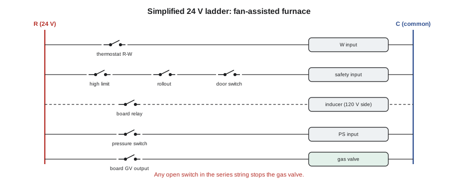
The sequence of operation of a typical fan-assisted furnace with hot surface ignition, from GAS-210 and GAS-220, is a favorite exam topic because every fault shows up as the step where it stops:
- The thermostat closes R to W. The board checks that the limit and rollout circuit is closed and the pressure switch is open, because a pressure switch already closed means it is stuck or jumpered.
- The board starts the inducer and waits for the pressure switch to close, proving that flue gas can leave. Then it pre-purges for a set time.
- The igniter is energized and warms up, typically for several seconds to a quarter of a minute depending on the board.
- The gas valve opens for the trial for ignition, typically about 4 to 7 seconds; the burners light and the flame sensor must prove the flame within the trial.
- Once flame is proven the igniter turns off. After a blower-on delay, typically 30 to 60 seconds, the circulating blower starts.
- When the call ends, the gas valve closes, the inducer post-purges, and the blower runs for its off delay, typically 90 to 180 seconds.
Ignition and flame sensing
Standing pilots burn all the time and heat a thermocouple, which produces a small DC voltage that holds the gas valve's pilot magnet open: typically 25 to 35 millivolts open circuit, about half that under load, and the magnet drops out at 1 to 2 millivolts. Intermittent pilot ignition lights a pilot with a spark on each call, proves it, and then opens the main valve. Hot surface ignition heats a silicon carbide or silicon nitride element until it glows and then opens the gas valve; silicon carbide igniters are fragile, typically 40 to 90 ohms cold, while silicon nitride resistances vary by model and the maker's range governs. Direct spark ignition sparks at the burner itself.
Most modern controls prove the flame by flame rectification. The board applies an AC voltage between the flame rod and the burner; because the flame conducts better in one direction, a small DC current, typically 2 to 6 microamps on a residential board, flows when the flame is present, and the board needs at least its minimum, often about 0.5 to 1 microamp. A weak signal comes from a dirty or oxidized rod, a poor burner ground, a rod out of the flame, or reversed polarity or a floating neutral, which GAS-220 found at the Beasley basement apartment. The rod is cleaned with a fine pad, not emery cloth. A signal of zero with the flame present points to the rod or its wiring; a flame that lights and then goes out at the end of the trial is the classic picture of a flame not being proven.
Worked problem
Reading the flame signal
On a call, a furnace lights, runs for about 6 seconds and shuts the gas valve, then retries and locks out after three attempts. The technician puts a microammeter in series with the flame rod wire and reads 0.3 µA during the brief flame. The board's minimum is 0.8 µA. What is happening, and what are the likely causes?
Show solution
- The flame lights, so gas, pressure and ignition are working.
- The valve closes at the end of the trial: the board is not proving the flame.
- 0.3 µA is below the 0.8 µA minimum.
Answer: The flame is not being proven. The likely causes are an oxidized or dirty flame rod, a rod not in the flame, a poor ground between burner and board, or a polarity or neutral problem at the supply. Clean the rod, check its position and the ground, check polarity, then measure again; GAS-220's Aberdeen boiler went from 0.3 to 2.6 µA once its pilot assembly was renewed.
The safety switches
Pressure switches prove that the inducer is moving flue gas. If one will not close, GAS-220's method applies: measure the suction at the switch and at the inducer tap. Good suction at the tap and poor at the switch means the tubing is cracked, kinked or waterlogged; poor at the tap means the inducer, the vent or a blocked heat exchanger or condensate trap. Limit switches open when the heat exchanger overheats, usually because of low airflow: dirty filters, closed registers, a slow blower. Most reset automatically, and repeated trips lock the board out. Rollout switches open when flame comes out of the burner area, which means the flue gas cannot get out. They are manual reset, and resetting one without finding the cause is how people get hurt. A jumpered safety switch, like the rollout at the Wentworth Street rental in GAS-220, is an immediate hazard.
Readings on paper
Because you cannot take a meter into the exam, troubleshooting questions describe readings and ask what they mean. Two rules from GAS-130 answer most of them. Measured across a closed switch, the voltage is close to zero, because there is no resistance to drop it across. Measured across an open switch in a live circuit, the voltage is the full supply voltage, because the switch is where the circuit is broken. Measured from a point to the common side, point-to-reference, the reading is the full supply voltage everywhere up to the open, and zero beyond it.
Worked problem
Finding the open on paper
A furnace's limit, rollout and door switches are in series between R and the board's safety input. With the thermostat calling, the technician reads 24 V from R to C, 24 V from the limit's outlet to C, 0 V from the rollout's outlet to C, and 24 V across the rollout switch itself. Which switch is open?
Show solution
- Up to the limit's outlet the reading to common is 24 V, so the limit is closed.
- After the rollout the reading is 0 V, so the circuit is broken at the rollout.
- Across the rollout switch the full 24 V appears, which is what an open switch shows.
Answer: The rollout switch is open. It is manual reset, and it opened because flame came out of the burner area, so the next step is to find out why the flue gas could not leave before the switch is reset.
Common mistakes
MistakeTrusting a non-contact tester or a zero reading without checking the meter.
InsteadTest live-dead-live with a meter rated for the circuit.
MistakeInstalling a new branch circuit or disconnect for a furnace yourself.
InsteadThat is electrical contractor work; the gas technician works on the appliance and its controls.
MistakeAdding loads to a control circuit without checking the transformer.
InsteadAdd the currents, multiply by 24 V and compare with the VA rating.
MistakeReplacing a board because a fault code named an input.
InsteadThe code names the input; test the device and wiring before blaming the board.
MistakeCleaning a flame rod with emery cloth.
InsteadUse a fine pad; then check the ground and polarity.
MistakeResetting a rollout switch and leaving.
InsteadFind out why flue gas could not leave before the appliance runs again.
Summary and key terms
- Ohm's law, V = I × R, and power, P = V × I, explain circuits; safety switches are in series, loads in parallel, and loose terminals heat as I² × R.
- Test live-dead-live with a CAT III meter; lock out before working in the cabinet.
- The 2023 NEC requires a furnace's own circuit and disconnect; Bayline leaves circuits and disconnects to licensed electrical contractors.
- A 40 VA transformer supplies about 1.67 A at 24 V.
- R to W calls for heat; C powers electronic thermostats; thermopiles make about 750 mV.
- The furnace sequence checks the limits and an open pressure switch, starts the inducer, proves draft, pre-purges, heats the igniter, opens the valve for a trial of about 4 to 7 s, proves flame and starts the blower after a delay.
- Thermocouples make 25 to 35 mV open circuit.
- Flame rectification gives typically 2 to 6 µA.
- Pressure switches prove draft, limits react to overheating, and rollouts are manual reset and mean flue gas could not leave.
- Ladder diagram
- A circuit drawing with the power lines as rails and each load and its switches as a rung.
- Volt-ampere (VA)
- The product of voltage and current, used to rate transformers.
- Trial for ignition
- The limited time the gas valve is held open for the flame to light and be proven before the control shuts it.
- Flame rectification
- Proving a flame by the small direct current that flows through it when an AC voltage is applied between a rod and the burner.
- Thermocouple
- Two joined dissimilar metals that produce a small voltage when heated, used to prove a standing pilot.
- Rollout switch
- A manual-reset switch near the burner that opens if flame comes out of the combustion area.
Practice problems
Work each problem on paper first, then reveal the answer to check.
Why are safety switches wired in series?
Show answer
So that any one of them opening stops the gas valve.
How much current can a 75 VA, 24 V transformer supply?
Show answer
75 ÷ 24 ≈ 3.1 A.
What does the board check before starting the inducer?
Show answer
That the limit circuit is closed and the pressure switch is open.
A flame lights and goes out at the end of the trial. What is not happening?
Show answer
The flame is not being proven.
What does good suction at the inducer tap but poor suction at the pressure switch mean?
Show answer
The tubing between them is cracked, kinked or blocked.
Lesson quiz · 5 questions
Score 60% or more to complete this lesson.
Create a free account to save your progress, take quizzes and earn a certificate.