
ELEC-130 · Lesson 4 of 12 · 30 min
Installing cable, boxes and devices
Most of the hours on a residential job are spent installing cable and boxes during rough-in and terminating devices at finish. The code sets the minimum requirements, but workmanship decides whether an installation is safe for decades: a cable stapled too tightly, a box with one conductor too many, or a loose terminal can each start a fire years later. This lesson covers the practical rules and good practice for non-metallic sheathed cable, boxes and their fill, protecting cables in the structure, making connections and terminating devices, and the sequence of rough-in and finish work.
Non-metallic sheathed cable
In the US, type NM-B cable is used in most one- and two-family dwellings. Its conductors are rated 90 °C, but its ampacity is limited to the 60 °C column, and it is permitted only in dry locations; damp and wet locations need type UF cable or conductors in raceway. Some jurisdictions restrict NM cable in larger or taller buildings.
Cable is identified by its conductor size and number: 14/2 means two insulated 14 AWG conductors plus a bare bonding (grounding) conductor; 14/3 has three insulated conductors (black, red and white) plus the bare conductor, used for three-way switching, split receptacles and multiwire circuits. Jacket colors help identify sizes on the job, with white often used for 14 AWG, yellow for 12 AWG and orange for 10 AWG, but the printing on the jacket is what counts.
Supporting and protecting cable
NM cable must be secured within 12 in of every box and at intervals of not more than 4½ ft, with staples or straps that do not damage the jacket. Where it runs through bored holes, the edge of the hole must be at least 1¼ in from the nearest edge of the framing member, or a steel plate at least 1/16 in thick must protect the cable from nails and screws.
- Staples hold the cable flat, never on edge, and are driven snug but not tight; a crushed jacket or nicked conductor can fail later.
- Cables are not stapled in bundles under one staple unless the staple is listed for it, and bundles of many current-carrying cables in insulation may need ampacity adjustment (ELEC-120).
- Cables are protected where they are exposed to damage, for example run along the face of basement walls below joists or in garages, using conduit or by running them through framing instead.
- Cables passing through metal studs need grommets to protect the jacket from sharp edges.
- Bends are gradual, with a radius of at least five times the cable diameter.
Worked problem
Planning staples
A cable runs 7.2 m along a joist from one box to another, both ends terminating in boxes. Using the Canadian rule (within 300 mm of each box and every 1.5 m), how many staples are needed at minimum?
Show solution
- One staple within 300 mm of each box: 2 staples, leaving 7.2 − 0.6 = 6.6 m between them.
- Supports every 1.5 m over 6.6 m: \(6.6/1.5 = 4.4\), so 4 more staples dividing the span into 5 sections of 1.32 m.
Answer: 6 staples. In practice, electricians add a few more so the cable runs neatly, and they never pull staples so tight that the jacket deforms.
Boxes
Every splice, device and luminaire connection must be in a box (or a fitting or enclosure listed for the purpose), and every box must remain accessible after the building is finished, never buried behind drywall.
- Device boxes hold switches and receptacles: single-gang and multi-gang, plastic (non-metallic) or metal, new-work (nailed to studs) or old-work (clamped into finished walls).
- Octagon and round boxes hold ceiling and wall luminaires; boxes for ceiling fans, or for luminaires heavier than a set limit, must be listed for that support.
- Square boxes with device rings are used where more volume is needed, for example where several cables meet.
- Vapor-barrier and airtight boxes are used in exterior walls and insulated ceilings (Lesson 2).
Boxes are mounted so that their front edge will be flush with the finished surface of combustible materials such as wood panelling, and set back no more than a small distance (typically 6 mm, or ¼ in) in non-combustible surfaces such as drywall, so that heat and arcs stay contained. Box extenders fix boxes set too deep.
Box fill
A box must be large enough for its conductors, devices, clamps and fittings, so that conductors are not crushed and heat can dissipate. ELEC-120 (Lesson 6) explained the calculation; in practice electricians count before they choose the box:
The NEC (314.16) counts each conductor originating outside the box as one, each device yoke as two conductors of the largest size connected to it, all equipment grounding conductors together as one, internal clamps as one, and luminaire studs or hickeys as one each; the total is multiplied by the volume allowance per conductor (2.00 in³ for 14 AWG, 2.25 in³ for 12 AWG).
Worked problem
Box fill for a receptacle box
Using the NEC method, a single-gang box contains one 14/2 cable entering and one 14/2 cable leaving (both with grounds), a duplex receptacle, and internal cable clamps. What volume is needed?
Show solution
- Insulated conductors: 2 + 2 = 4.
- Grounding conductors: all together count as 1.
- Receptacle yoke: 2. Internal clamps: 1.
- Total: 8 conductor volumes × 2.00 in³ = 16.0 in³.
Answer: 16.0 in³ (about 262 cm³). A standard 18 in³ single-gang plastic box is enough; a shallow 12.5 in³ box is not. Boxes are marked with their volume.
Making connections
Most residential faults that cause fires begin at connections. Good connections are tight, use connectors and terminals listed for the conductors, and do not stress the conductors:
- Strip only the length the connector or terminal needs, without nicking the conductor.
- Twist-on wire connectors: pre-twist conductors if the manufacturer recommends, choose the connector for the number and sizes of conductors, and turn until tight; no bare copper should show below the skirt.
- Lever-type and push-in connectors are listed for specific conductor sizes and types; follow their markings.
- Leave enough free conductor in each box to make connections and replace devices: at least about 150 mm (6 in) of free conductor, with some extending beyond the box opening.
- Fold conductors neatly into the box, with bonding conductors connected together and to every metal box and device yoke as required.
Terminating devices
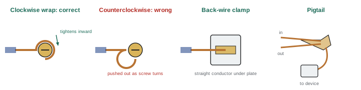
- Screw terminals: wrap the conductor clockwise (the direction the screw tightens) about three-quarters of the way around, and tighten firmly. Only one conductor goes under a screw unless the device is marked for two.
- Back-wire clamps (pressure-plate terminals) accept a straight stripped conductor under a plate tightened by the screw, and are reliable for one or two conductors as marked.
- Push-in ("backstab") terminals, where allowed, accept only solid 14 AWG copper on most devices and have a higher rate of failure under load than screw terminals; many electricians avoid them.
- Torque: where the manufacturer specifies a torque, use a calibrated torque screwdriver; this is required at breakers and panels and good practice everywhere.
- Pigtails: rather than using a receptacle to pass current to the next outlet, splice the circuit conductors together with a short pigtail to the device. A failed or loose receptacle then does not interrupt or overheat the rest of the circuit, and multiwire circuits must use pigtails for the neutral so that removing a device does not open the shared neutral (ELEC-120).
The NEC requires terminals to be identified for the conductor material; aluminum branch-circuit conductors may connect only to devices marked CO/ALR (for 15 A and 20 A receptacles and switches) or with listed connectors (Lesson 11).
Rough-in and finish
Residential electrical work is done in two main stages around the other trades:
- Rough-in: after framing, plumbing and ductwork are in place and before insulation and drywall, the electrician installs boxes, runs and staples cables, makes up grounds and splices in boxes (often called "making up"), installs the panel and services where scheduled, and calls for the rough-in inspection. Low-voltage cabling (data, coaxial, alarms, Lesson 12) is usually roughed in at the same time.
- Finish (trim-out): after drywall and paint, the electrician installs devices, cover plates, luminaires, fans, appliances connections and breakers, labels the panel, tests everything (Lesson 9), and calls for the final inspection.
Between the two, the electrician protects work from damage: marking box locations so drywall installers do not cover them, and checking that insulation installers have not pulled cables from staples or packed insulation around recessed lights not rated for contact (IC rating).
Worked problem
Rough-in checklist for one room
List what an electrician checks in a bedroom before calling for rough-in inspection.
Show solution
- Boxes at the planned locations and heights, securely fastened, set to the finished wall thickness, sealed to the air barrier where in exterior walls.
- Cables stapled at the required intervals and near boxes, protected where within the set distance of framing faces, with enough free conductor in each box.
- Bonding conductors joined and connected to metal boxes; splices made up neatly where required at this stage.
- Cables labeled at the panel end with their circuit, and the box count within fill limits.
Answer: These checks match what inspectors look for. Catching problems now, before drywall, costs minutes; finding them after costs holes in finished walls.
Luminaires, fans and recessed lights
Lighting outlets have their own installation details:
- Ceiling boxes must support the luminaire. Light luminaires hang from the box's mounting strap; heavier ones and all ceiling fans need boxes or braces listed for the weight or for fan support, fastened to framing, because a fan's motion loosens ordinary boxes.
- Recessed luminaires (pot lights) in insulated ceilings must be rated IC (for contact with insulation) or kept the required distance from insulation; in cold climates they should also be airtight (often marked IC and AT), or they leak warm moist air into the attic. Many current LED recessed fixtures are thin "wafer" lights with a remote driver box, which must remain accessible.
- Luminaires in damp or wet locations (bathroom showers, covered porches, outdoors) must be marked for that location.
- Closet luminaires must keep set clearances from storage areas, and incandescent lamps without enclosures are generally not allowed in closets.
- Under-cabinet and strip lighting often uses low-voltage LED tape with a Class 2 driver; the driver location and the cable from it are planned at rough-in.
Worked problem
Recessed lights in a cathedral ceiling
An owner wants eight recessed lights in a vaulted ceiling insulated to the roof deck, in a cold climate. What type should be used, and why?
Show solution
- The fixtures will be in direct contact with insulation: they must be IC rated.
- Warm indoor air leaking into the roof assembly would condense on the cold deck: they must be airtight (AT).
- Thin LED wafer fixtures need little depth, which helps in shallow rafter spaces.
Answer: IC- and AT-rated LED fixtures, typically wafer types with accessible drivers. Using non-IC fixtures here would be a fire hazard, and non-airtight fixtures a moisture problem.
Common mistakes
MistakeStapling cable on edge or so tightly that the jacket deforms.
InsteadStaple flat and snug, never crushing the jacket.
MistakeLeaving cables unprotected close to the face of studs.
InsteadKeep the set distance from framing faces or install steel plates.
MistakeChoosing boxes without counting fill.
InsteadCount conductors, devices, clamps and grounds, and choose a box with enough volume.
MistakeWrapping conductors counterclockwise under screws.
InsteadWrap clockwise so tightening draws the conductor in.
MistakeUsing devices as splice points for the rest of the circuit.
InsteadUse pigtails, especially for shared neutrals.
Summary and key terms
- Non-metallic sheathed cable is limited to dry locations and to its 60 °C ampacity.
- Support cable near boxes and at set intervals; protect it from nails, screws and sharp edges.
- Every splice is in an accessible box, mounted flush or within the permitted setback.
- Count box fill before choosing the box.
- Make tight, listed connections; wrap clockwise; prefer screw or clamp terminals; use pigtails.
- Rough-in and finish stages bracket the other trades; protect work in between.
- NMD90 / NM-B
- Non-metallic sheathed cable used in dwellings in Canada and the US.
- 14/2 cable
- Two insulated 14 AWG conductors plus a bare bonding conductor.
- Staple
- A fastener that supports cable to framing.
- Steel plate
- Protection for cable near the face of framing.
- Device box
- A box for switches and receptacles.
- Box fill
- The volume required for a box's contents.
- Pigtail
- A short conductor joining circuit conductors to a device terminal.
- Back-wire clamp
- A terminal clamping a straight conductor under a plate.
- Rough-in
- Installing boxes and cables before walls are closed.
- Finish
- Installing devices, luminaires and covers after walls are finished.
Practice problems
Work each problem on paper first, then reveal the answer to check.
What does 12/3 cable contain?
Show answer
Three insulated 12 AWG conductors and a bare bonding conductor.
Which ampacity column applies to NM cable?
Show answer
60 °C.
Why must cable be kept back from framing faces or protected?
Show answer
To prevent damage from drywall screws and nails.
Minimum bend radius for a cable 10 mm thick?
Show answer
50 mm (5 × diameter).
NEC box fill: two 12/2 cables in, one switch, clamps. Volume?
Show answer
(4 + 1 + 2 + 1) × 2.25 = 18.0 in³.
Why mount boxes flush with combustible surfaces?
Show answer
To contain heat and arcs within the box.
Direction to wrap a conductor under a terminal screw?
Show answer
Clockwise.
Why use pigtails for shared neutrals?
Show answer
Removing a device must not open the neutral of a multiwire circuit.
What is checked after insulation is installed?
Show answer
Cables still stapled; recessed lights rated for contact; boxes accessible.
Free conductor to leave in each box?
Show answer
About 150 mm (6 in).
Lesson quiz · 5 questions
Score 60% or more to complete this lesson.
Create a free account to save your progress, take quizzes and earn a certificate.