
ELEC-120 · Lesson 9 of 12 · 28 min
Grounding and bonding
Grounding and bonding are the parts of the code most often misunderstood, by homeowners, by apprentices and sometimes by experienced electricians. They are also among the most important for safety, because they decide what happens when something goes wrong: when a hot conductor touches a metal box, when lightning strikes a line, or when a transformer fails. A properly grounded and bonded system makes a fault trip the breaker in a fraction of a second. A poorly bonded one can leave a metal appliance or water pipe energized at a lethal voltage, silently, until someone touches it.
In the NEC, grounding and bonding are covered in Article 250, one of the longest articles in the code. Key tables are Table 250.66 (grounding electrode conductor sizes) and Table 250.122 (equipment grounding conductor sizes). This chapter explains the principles and the main rules; always confirm the details in the edition your jurisdiction has adopted.
Two different jobs
Grounding and bonding are related but different, and keeping them separate in your mind solves most confusion:
- Grounding connects the electrical system to the earth. Its purposes are to limit the voltage imposed by lightning, line surges and accidental contact with higher-voltage lines, and to stabilize the system voltage relative to earth during normal operation.
- Bonding connects all the non-current-carrying metal parts (enclosures, raceways, equipment frames, metal piping) to each other and back to the source, through a low-impedance path. Its purpose is to carry fault current back to the source quickly so that the overcurrent device trips, and to keep all metal parts at the same potential so that a person touching two of them is not shocked.
The single most important fact in this chapter: the earth is not a good path for fault current. Clearing a fault depends on bonding, a conductor path back to the source, not on the ground rod.
System grounding at the service
In a typical North American system, the utility transformer's secondary has a center point (neutral) that is grounded at the transformer. At the building's service, the neutral is grounded again and connected to the equipment bonding system at one point. This connection is what lets fault current return to the source: a fault from a hot conductor to a metal enclosure flows through the bonding path to the service, across the neutral-to-ground connection, and back to the transformer on the neutral, a low-impedance loop that trips the breaker.
At the service, the grounded (neutral) conductor is connected to the service equipment enclosure by the main bonding jumper (250.24 and 250.28), and to the grounding electrode system by the grounding electrode conductor. Downstream of the service, the neutral and the equipment grounding conductors must be kept separate: in subpanels, the neutral bar is isolated from the enclosure and the equipment grounding conductor is bonded to it (250.24(A)(5) and 250.142(B)).
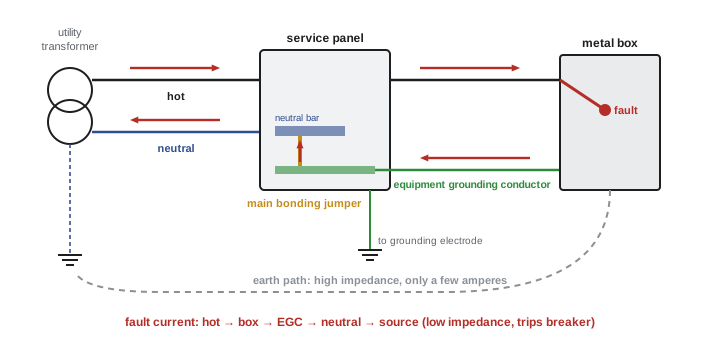
Why only one neutral-to-ground connection?
If the neutral were bonded to ground again at a subpanel, normal neutral current would divide: some would flow on the neutral and some on the bonding conductors, metal raceways, cable armor and even water pipes. Metal parts would then carry current all the time, creating shock risk, electrical noise, overheating of small bonding paths, and false trips of ground fault protection. This is why the code insists on a single bond at the service (or at each separately derived system), and why a four-wire feeder (two hots, neutral and bonding conductor) is required to subpanels.
Worked problem
A subpanel wiring error
An inspector finds a subpanel in a garage where the neutral bar is bonded to the enclosure with its green bonding screw, and the feeder has a separate bonding conductor. What is wrong, and what is the fix?
Show solution
- The neutral is bonded to ground at the subpanel as well as at the service: two bonding points.
- Neutral current now returns partly on the bonding conductor and any metal paths in parallel with it.
- Fix: remove the bonding screw or strap so the neutral bar is isolated from the enclosure; land the feeder's bonding conductor on a bonding bar connected to the enclosure.
Answer: The subpanel should have an isolated neutral and a bonded enclosure. The bonding screw supplied with many panels is only for use when the panel is service equipment.
Grounding electrodes
The grounding electrode is the physical connection to the earth. A building usually uses several electrodes bonded together into a grounding electrode system.
Section 250.50 requires all electrodes present at a building to be bonded together into a grounding electrode system: metal underground water pipe in contact with the earth for at least 3.0 m (10 ft), which must always be supplemented by another electrode; the metal frame of the building where effectively grounded; a concrete-encased electrode (at least 6.0 m, 20 ft, of reinforcing bar or 4 AWG bare copper in a footing); a ground ring; and rod, pipe or plate electrodes. A rod must be at least 2.44 m (8 ft) long; a single rod must be supplemented by a second electrode, at least 1.8 m (6 ft) away, unless it is shown to have a resistance to earth of 25 Ω or less (250.53(A)). The grounding electrode conductor is sized from Table 250.66 according to the size of the service conductors, but the conductor to a rod need not be larger than 6 AWG copper and to a concrete-encased electrode not larger than 4 AWG copper.
The concrete-encased electrode, often called a Ufer ground after the engineer who developed it during the Second World War, is usually the best electrode available, because concrete in contact with the earth holds moisture and presents a large contact area. Designers and electricians should arrange to connect to the footing reinforcement before the concrete is poured; afterwards the opportunity is lost.
Grounding electrodes have a resistance to earth of a few ohms at best, and often 10 to 100 Ω. That is fine for their job (limiting voltages from lightning and surges, and stabilizing the system) but far too high to carry fault current that will trip a breaker, as the next example shows.
The effective fault current path
Worked problem
Why bonding, not the earth, clears a fault
A 120 V branch circuit runs 100 ft in 12 AWG copper (about 2.0 Ω per 1000 ft at operating temperature) to a metal box. The hot conductor faults to the box. Assume 0.05 Ω of source impedance. (a) With a 12 AWG equipment grounding conductor back to the panel, what current flows? (b) If the equipment grounding conductor were missing and the box were connected only to a ground rod of 25 Ω (with about 5 Ω through the earth back to the utility ground), what current would flow, and what voltage would the box have?
Show solution
- (a) Hot: \(0.100 \times 2.0 = 0.20\) Ω; equipment grounding conductor the same. Loop: \(0.20 + 0.20 + 0.05 = 0.45\) Ω. Current: \(120/0.45 = 267\) A.
- About 270 A is more than 13 times the rating of a 20 A breaker, enough to trip its instantaneous (magnetic) element in a fraction of a second.
- (b) Loop: \(0.20 + 25 + 5 \approx 30.2\) Ω. Current: \(120/30.2 = 4.0\) A.
- A 20 A breaker will never trip on 4 A. The box sits at about \(4.0 \times 25 = 99\) V relative to the earth nearby.
Answer: With a proper bonding conductor, about 270 A flows and the breaker clears the fault almost instantly. Through the earth alone, only about 4 A flows, the breaker holds, and the box stays energized at nearly 100 V indefinitely, a lethal shock hazard. Bonding, not grounding, clears faults.
Equipment grounding conductors are sized from Table 250.122 according to the rating of the overcurrent device: for copper, 14 AWG for 15 A, 12 AWG for 20 A, 10 AWG for 30 to 60 A, 8 AWG for 100 A, 6 AWG for 200 A, 4 AWG for 300 A and 3 AWG for 400 A. A metal raceway such as EMT or rigid conduit can serve as the equipment grounding conductor (250.118), provided every joint and connector is tight; in non-metallic raceways and cables, a separate conductor is installed. If circuit conductors are increased in size for voltage drop, the equipment grounding conductor must be increased proportionally (250.122(B)).
Bonding other metal systems
Any metal system that could become energized must be bonded so that it cannot rise to a dangerous voltage. This includes metal water piping, gas piping (bonded, but never used as an electrode), structural steel, metal ducts in some cases, and, in pools and spas, the entire area around the water (an equipotential bonding grid covered in later courses). At the service, extra care is taken because the fault currents are highest and the service conductors have no overcurrent protection on the line side: service raceways are bonded with bonding bushings or jumpers, not relying on locknuts alone.
The NEC requires metal water piping to be bonded to the service (250.104(A)), and other metal piping likely to become energized, such as gas piping, to be bonded to the equipment grounding conductor of the circuit likely to energize it (250.104(B)). Gas piping must never be used as a grounding electrode (250.52(B)).
Separately derived systems
A transformer, generator or other source whose output conductors have no direct electrical connection to the supply conductors creates a new system. That system needs its own neutral-to-ground connection (a system bonding jumper) and its own connection to a grounding electrode, at the source or at its first disconnecting means. A dry-type transformer in a commercial building that steps 600 V or 480 V down to 120/208 V is the most common example. Treating its secondary like a subpanel, with no neutral-to-ground bond, leaves the secondary ungrounded and faults on it would not trip the breakers.
GFCI, AFCI and isolated grounds
Ground fault circuit interrupters (GFCIs) protect people, not equipment. A GFCI compares the current on the hot and neutral conductors; if they differ by about 5 mA (Class A devices trip at 4 to 6 mA), current is leaking somewhere, possibly through a person, and the device opens the circuit within a fraction of a second. A GFCI works even without a bonding conductor, which is why it is accepted as a way to replace old two-wire receptacles in some cases, but it does not replace bonding for clearing faults to metal. Arc fault circuit interrupters (AFCIs) detect the electrical signature of arcing in damaged cords and wiring and are required for many dwelling circuits; ELEC-130 covers where each is required.
An isolated ground receptacle (marked with an orange triangle) has its grounding terminal insulated from its mounting strap, so that a separate insulated grounding conductor can be run back to the panel for sensitive electronic equipment, reducing electrical noise. The metal box must still be bonded in the normal way.
Lesson 12 applies these rules to a complete installation, including the grounding electrode and isolated neutral at a detached building.
Common mistakes
MistakeBelieving the ground rod will trip the breaker during a fault.
InsteadEarth resistance is far too high; the bonding conductor path back to the source clears faults.
MistakeBonding neutral to ground in a subpanel.
InsteadBond neutral to ground only at the service or at a separately derived system; isolate the neutral in subpanels.
MistakeRunning a three-wire feeder (no bonding conductor) to a new subpanel.
InsteadUse a four-wire feeder with a separate bonding (equipment grounding) conductor.
MistakeUsing gas piping as a grounding electrode.
InsteadGas piping is bonded but never used as an electrode.
MistakeForgetting to ground and bond a transformer secondary.
InsteadEach separately derived system needs its own system bonding jumper and grounding electrode connection.
Summary and key terms
- Grounding connects the system to earth to limit surge voltages and stabilize it; bonding connects metal parts into a low-impedance fault path back to the source.
- The earth is a poor fault path: a fault through a 25 Ω rod draws only a few amperes and will not trip a breaker.
- The neutral is bonded to ground at one point only: the service, or each separately derived system.
- Subpanels have an isolated neutral, a bonded enclosure and a four-wire feeder.
- All electrodes present are bonded into a system (250.50); a single rod needs a supplemental electrode unless 25 Ω or less; GEC from Table 250.66.
- EGCs are sized from Table 250.122 by overcurrent device rating and increased proportionally with upsized conductors; metal raceways may serve as EGCs.
- Bond metal water and gas piping, structural steel and service raceways; never use gas piping as an electrode.
- GFCIs trip at about 5 mA to protect people; isolated ground receptacles reduce noise but do not replace bonding.
- Grounding
- Connecting the electrical system to the earth through the grounding electrode system.
- Bonding
- Connecting metal parts to establish electrical continuity and conductivity.
- Grounding electrode system
- All grounding electrodes at a building bonded together.
- Concrete-encased electrode
- Reinforcing bar or bare copper in a concrete footing used as a grounding electrode (a Ufer ground).
- Grounding electrode conductor
- The conductor connecting the system to the grounding electrode system.
- Equipment grounding conductor
- The conductor connecting non-current-carrying metal parts back to the source, providing the fault path.
- Main bonding jumper
- The connection between the grounded conductor and the equipment grounding conductor at the service.
- System bonding jumper
- The neutral-to-ground connection of a separately derived system.
- Separately derived system
- A system supplied by a transformer or generator with no direct connection to the supply conductors.
- Effective ground-fault current path
- A low-impedance path designed to carry fault current back to the source.
- GFCI
- Ground-fault circuit interrupter: a device that trips on a small difference between hot and neutral current.
Practice problems
Work each problem on paper first, then reveal the answer to check.
State the main purpose of grounding and the main purpose of bonding.
Show answer
Grounding limits voltages from lightning, surges and contact with higher-voltage lines and stabilizes the system; bonding provides a low-impedance fault path so overcurrent devices trip, and keeps metal parts at the same potential.
A 240 V fault from a hot conductor to a metal enclosure has a loop impedance of 0.3 Ω. What current flows, and will a 40 A breaker trip quickly?
Show answer
240/0.3 = 800 A, 20 times the rating: yes, on its instantaneous element.
Without a bonding conductor, the same enclosure connects to a 50 Ω ground rod. Roughly what current flows (ignore other resistances)?
Show answer
About 240/50 = 4.8 A: the breaker will not trip.
Where should the neutral be bonded to the enclosure in a building with a main panel and two subpanels?
Show answer
Only at the main (service) panel; the subpanels have isolated neutrals and bonded enclosures.
Why does a feeder to a detached garage subpanel need four conductors in a modern installation?
Show answer
Two hots, a neutral and a separate bonding (equipment grounding) conductor, so the neutral and bonding paths stay separate downstream of the service.
What size copper equipment grounding conductor is required for a 60 A circuit, and for a 200 A feeder?
Show answer
Table 250.122: 10 AWG copper for 60 A; 6 AWG copper for 200 A.
Why is a concrete-encased electrode usually better than a single ground rod?
Show answer
It has a large contact area with moist earth through the concrete, giving a lower and more stable resistance to earth.
A 600 V to 120/208 V dry-type transformer feeds a panel. What grounding and bonding does its secondary need?
Show answer
A system bonding jumper connecting the secondary neutral to ground at the transformer or first disconnect, a grounding electrode conductor to the building's grounding electrode system, and bonding of the enclosure.
At what current does a Class A GFCI trip, and does it need a bonding conductor to work?
Show answer
About 4–6 mA of imbalance; no, it compares hot and neutral currents and works without a bonding conductor.
Why must gas piping be bonded but never used as a grounding electrode?
Show answer
Bonding keeps it from becoming energized; using it as an electrode would deliberately pass current through gas piping, risking arcing at joints and corrosion.
Lesson quiz · 5 questions
Score 60% or more to complete this lesson.
Create a free account to save your progress, take quizzes and earn a certificate.