
ELEC-120 · Lesson 7 of 12 · 33 min
Switches, receptacles and luminaires
The devices at the end of branch circuits are what people actually touch: switches on walls, receptacles for plugs and the luminaires that light rooms. They are installed by the thousand on every job, and small errors repeated across a building become large problems: a switch in the neutral leaves a fixture live when "off", a reversed receptacle energizes the shell of a lamp socket, a recessed light buried in insulation overheats. This lesson covers the code rules and good practice for switches, receptacles and luminaires, including the wiring of three-way and four-way switching, device ratings, tamper-resistant and weather-resistant receptacles, and the support, clearance and thermal requirements of luminaires.
In the National Electrical Code, switches are covered by Article 404, receptacles by Article 406 and luminaires by Article 410, with dimmers and lighting controls throughout.
Switches
A switch must open the ungrounded (hot) conductor, never the grounded (neutral) conductor alone. A switch in the neutral turns the light off, but leaves the lamp socket and wiring live, waiting for someone changing a lamp to complete the circuit through their body.
Switch ratings
General-use snap switches are rated in amperes and volts for AC circuits. They may control resistive and inductive loads up to their full rating and tungsten-filament lamps up to their rating, but motor loads only up to 80% of the switch rating unless the switch carries a horsepower rating. Switches for special duty are marked accordingly (for example, T-rated for tungsten lamps, horsepower-rated for motors).
Worked problem
Switching a motor load
A 15 A, 120 V general-use snap switch is proposed to control a 120 V exhaust fan whose motor draws 13 A. Is it acceptable?
Show solution
- Limit for motor loads: \(0.80 \times 15 = 12\) A.
- The fan draws 13 A, more than 12 A.
Answer: No. Use a 20 A switch (limit 16 A for motors) or a switch with a horsepower rating at least that of the fan motor. Switch contacts arc when interrupting inductive motor current, which is why the derating applies.
Three-way and four-way switching
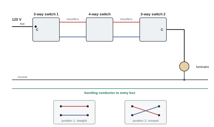
Controlling a light from two locations uses two three-way switches, each with a common terminal and two traveler terminals; from three or more locations, four-way switches are added between them. The hot conductor goes to the common of the first three-way switch, two travelers connect the three-way switches (through any four-ways), and the common of the last switch feeds the light. The neutral goes directly to the light.
Worked problem
Conductors for multi-location switching
A light is controlled from three locations using two three-way switches and one four-way switch, wired with cable. Count the insulated conductors needed (a) between the two switch locations nearest each other, (b) to the luminaire from the last switch, if the neutral must also be available at every switch location.
Show solution
- Between switches: two travelers, plus a neutral for future smart switches: 3 conductors (for example a 3-conductor cable with bonding conductor).
- From the last switch to the luminaire: switched hot plus neutral: 2 conductors.
Answer: Three insulated conductors between switch locations (two travelers and a neutral) and two to the luminaire. Many codes now require a neutral at most switch locations, because electronic switches, occupancy sensors and smart dimmers need it to power their electronics; check the edition in force.
The NEC (404.2(B)) prohibits switches from disconnecting the grounded conductor alone, and 404.2(C) requires a grounded conductor at most switch locations controlling lighting loads, so that electronic lighting controls can be installed.
Dimmers
Dimmers must match the load type: incandescent, electronic low voltage, magnetic low voltage, LED or fluorescent. LED lamps and drivers are not all dimmable, and those that are may need a specific dimmer type (leading-edge or trailing-edge phase control, or 0–10 V control wiring) to dim smoothly without flicker. Dimmers also have a maximum load, which is reduced when several are ganged in one box because their heat-sink fins must be removed.
Receptacles
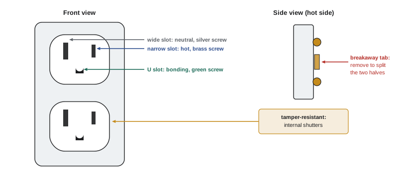
Receptacles must be installed with the correct polarity: the narrow slot connected to the hot conductor (brass screw), the wide slot to the neutral (silver screw) and the U-shaped slot to the bonding conductor (green screw). Reversed polarity leaves the shell of a lamp socket or the case of an appliance connected to the hot conductor even when its switch is off.
- Grounding-type receptacles are required on new circuits, and each must be bonded to the equipment bonding conductor. Self-grounding receptacles and bonding jumpers from the box ensure the connection.
- Tamper-resistant receptacles have internal shutters that open only when both prongs are inserted at once, preventing children from inserting objects. They are required in dwellings and many other locations frequented by children.
- Weather-resistant receptacles, made of UV-stable and corrosion-resistant materials, are required in damp and wet locations, with covers suitable for the location (Lesson 10).
- GFCI and AFCI receptacles combine protection with the receptacle (Lesson 9 and ELEC-130).
- Receptacles mounted face-up in countertops or floors must be listed for that use.
Worked problem
Testing a receptacle
With a voltmeter at a 120 V receptacle, an electrician measures: narrow slot to wide slot 0 V, narrow slot to U-ground 0 V, wide slot to U-ground 120 V. What is wrong?
Show solution
- In a correct receptacle, narrow to wide and narrow to ground are both about 120 V, and wide to ground is about 0 V.
- Here the 120 V appears between the wide slot and ground: the wide slot is connected to the hot conductor.
- Narrow to wide reading 0 V means the narrow slot is connected to the neutral.
Answer: Reversed polarity: hot and neutral are swapped at the receptacle (or upstream). It must be corrected before the receptacle is used; plug-in testers find this instantly, and many inspectors check every receptacle.
Luminaires
Support
Luminaires must be securely supported, independently of their supply conductors. Outlet boxes are designed to support luminaires up to a limited weight (commonly about 23 kg, or 50 lb); heavier luminaires need independent support from the building structure. Ceiling fans need boxes listed for fan support, because their motion and weight loosen ordinary boxes.
Heat and clearances
Luminaires produce heat, and most luminaire fires come from heat trapped where it cannot escape:
- Recessed luminaires (pot lights) are either IC-rated, approved for direct contact with thermal insulation, or non-IC, which must be kept clear of insulation by a specified distance (typically 76 mm, 3 in) and from combustible material. Both types usually include a thermal protector that switches the lamp off if it overheats.
- Luminaires in clothes closets must be of permitted types (enclosed lamps, recessed or surface-mounted LED or fluorescent) and kept at minimum distances from the storage space, so that clothing cannot touch hot lamps.
- Luminaires must be marked for their location: damp-location or wet-location ratings for bathrooms, exteriors and showers.
- Supply conductors must be rated for the temperature inside the luminaire, often 90 °C, which affects the choice of cable near some luminaires.
The NEC (Article 410) sets requirements for luminaire support (410.30 and 314.27), recessed luminaires and thermal insulation (410.116), luminaires in clothes closets (410.16: open lamps are not permitted, and surface-mounted luminaires with enclosed incandescent or LED light sources need 300 mm (12 in) clearance from the storage space, fluorescent and LED types identified for the purpose 150 mm (6 in)), and wet and damp locations (410.10).
Worked problem
Too heavy for the box
A decorative chandelier weighs 32 kg (70 lb). The ceiling outlet box is marked for luminaires up to 23 kg (50 lb). What must the electrician do?
Show solution
- The luminaire exceeds the box's marked rating.
- It must be supported independently of the box, for example by a listed support bracket fastened to the structure, or a box listed for the weight.
Answer: Provide independent support or a box listed for at least 32 kg. Falling luminaires injure people, and ceiling boxes in finished buildings are often fastened only to drywall or a light bracket.
LED lighting and controls
LED luminaires use electronic drivers that convert line voltage to a constant current for the LEDs. They draw much less power than older lamps but have high inrush currents at switch-on and, with many drivers on one circuit, can trip breakers or weld switch contacts; manufacturers give the maximum number of drivers per circuit. Lighting controls such as occupancy sensors and daylight dimming are increasingly required by energy codes, which interact with the electrical code in the choice of devices and the wiring needed (for example, the neutral at switch locations).
Ground-fault and arc-fault protective devices
Many receptacles and circuits must be protected by devices that respond to faults an ordinary breaker cannot see. A ground-fault circuit interrupter (GFCI) compares the current leaving on the hot conductor with the current returning on the neutral; if they differ by about 5 mA (Class A devices trip between 4 and 6 mA), some current must be flowing through another path, possibly a person, and the device opens the circuit within a fraction of a second. An arc-fault circuit interrupter (AFCI) monitors the waveform of the current for the signatures of arcing, such as a damaged cord or a loose connection inside a wall, which can start a fire at currents far too small to trip a breaker.
These functions come in several forms: breakers in the panel, receptacles at the first outlet, blank-face devices with no receptacle, and dual-function devices that provide both GFCI and AFCI protection. Which form to use is a design choice, within the rules of the code and the conditions of the installation.
Line and load terminals
A GFCI receptacle has two pairs of terminals. The supply connects to the LINE terminals; receptacles connected to the LOAD terminals downstream are protected as well. This allows one GFCI receptacle to protect a whole run of ordinary receptacles, which must then be marked "GFCI protected" (stickers are supplied with the device). Reversing line and load is a common error; modern devices will not reset if wired backwards, but older ones could leave the face receptacle unprotected.
Worked problem
Choosing where to put a GFCI
A garage circuit feeds five receptacles in a chain, R1 (nearest the panel) to R5. All five need ground-fault protection. Where should a single GFCI receptacle go, and how are the others wired?
Show solution
- Install the GFCI at R1, the first outlet on the circuit, with the supply cable on its LINE terminals.
- Connect the cable to R2 to the LOAD terminals; R2 to R5 are then protected.
- Mark R2 to R5 "GFCI protected".
Answer: One GFCI receptacle at R1 protects all five. A GFCI breaker in the panel would do the same, and also protect the cable, at a higher cost and with the reset button away from the work area.
Nuisance tripping and testing
A GFCI that trips repeatedly is usually telling the truth: moisture in an outdoor box, a damaged tool cord or a shared neutral between two circuits (a neutral from one GFCI-protected circuit landed on another circuit) are common causes. Long runs of cable and some electronic loads can add small leakage currents that together approach the trip level. Every GFCI and AFCI has a test button, and manufacturers recommend pressing it regularly; the device should trip and then reset. A plug-in tester with a GFCI test button checks protection at downstream receptacles.
In the NEC, GFCI requirements appear in 210.8 for dwelling and other occupancies, and AFCI requirements in 210.12, which covers most 120 V, 15 A and 20 A branch circuits in dwelling-unit living areas, kitchens and laundry areas.
Common mistakes
MistakeSwitching the neutral.
InsteadSwitches must open the ungrounded conductor.
MistakeControlling motor loads with general-use switches at full rating.
InsteadLimit motor loads to 80% or use horsepower-rated switches.
MistakeWiring receptacles with reversed polarity.
InsteadHot to the narrow slot (brass), neutral to the wide slot (silver); test every receptacle.
MistakeBurying non-IC recessed luminaires in insulation.
InsteadUse IC-rated luminaires or maintain the required clearances.
MistakeHanging heavy luminaires or ceiling fans from ordinary boxes.
InsteadUse boxes listed for the weight or for fan support, or independent support.
Summary and key terms
- Switches open the ungrounded conductor; general-use switches control motors only to 80% of rating.
- Three-way and four-way switches use travelers between switches; the neutral goes to the light.
- A neutral is now commonly required at switch locations for electronic controls.
- Receptacles need correct polarity, bonding, and tamper-resistant or weather-resistant types where required.
- Luminaires need proper support, heat clearances, location ratings and suitable supply conductors.
- LED drivers bring inrush and dimming compatibility issues.
- Snap switch
- A general-use switch operated by a toggle or rocker.
- Three-way switch
- A switch with a common and two traveler terminals.
- Four-way switch
- A switch that reverses two travelers, used between three-way switches.
- Traveler
- A conductor running between multi-location switches.
- Polarity
- The correct connection of hot and neutral to device terminals.
- Tamper-resistant receptacle
- A receptacle with shutters that open only to a proper plug.
- Weather-resistant receptacle
- A receptacle made for damp and wet locations.
- IC-rated luminaire
- A recessed luminaire approved for contact with insulation.
- Thermal protector
- A device in a luminaire that opens if it overheats.
- Driver
- The power supply that converts line voltage for LEDs.
Practice problems
Work each problem on paper first, then reveal the answer to check.
Why must switches open the hot conductor?
Show answer
So the controlled equipment is not live when switched off.
Maximum motor load on a 20 A general-use snap switch?
Show answer
16 A.
How many three-way and four-way switches control a light from four locations?
Show answer
Two three-way and two four-way switches.
Why are neutrals required at many switch boxes?
Show answer
Electronic switches and sensors need power for their electronics.
Which slot of a 5-15R connects to the hot conductor?
Show answer
The narrow slot (brass screw).
Narrow to ground reads 120 V, wide to ground 0 V. Polarity?
Show answer
Correct.
What does a tamper-resistant receptacle prevent?
Show answer
Objects being inserted into one slot.
May a non-IC recessed luminaire touch insulation?
Show answer
No; it needs the specified clearance.
A box is marked for 23 kg. Can it hold a 15 kg luminaire?
Show answer
Yes.
Why limit the number of LED drivers on one circuit?
Show answer
Their combined inrush current can trip breakers or damage switches.
Lesson quiz · 5 questions
Score 60% or more to complete this lesson.
Create a free account to save your progress, take quizzes and earn a certificate.