
ELEC-120 · Lesson 3 of 12 · 29 min
Branch circuits
A branch circuit is the final link in an electrical system: the conductors between the last overcurrent device and the outlets, where lights, receptacles and equipment connect. Most of an electrician's working day is spent installing, extending and troubleshooting branch circuits, and most of the code questions that arise on site are about them: how many receptacles may go on one circuit, what rating of receptacle suits a 20 A circuit, how much continuous load a circuit may carry, and what is required when two circuits share a neutral. This lesson introduces the rules that govern branch circuits; Lesson 4 then sizes their conductors, and ELEC-130 applies them to dwellings.
In the National Electrical Code, branch circuits are covered by Article 210 (ratings, outlets required, GFCI and AFCI protection, multiwire circuits) and the load calculation methods of Article 220; receptacles are in Article 406.
Branch circuits, feeders and services
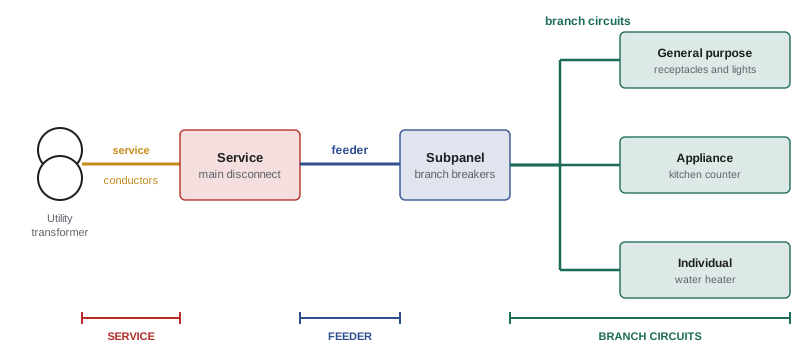
The code distinguishes three kinds of circuit by where they sit in the system:
- The service: conductors and equipment that bring power from the utility to the building and contain its main disconnecting means.
- Feeders: circuits from the service equipment (or another power source, such as a transformer) to a panelboard or other distribution point.
- Branch circuits: circuits from the final overcurrent device to the outlets.
Branch circuits are further described by what they supply: a general-purpose branch circuit supplies several outlets for lights and appliances; an appliance branch circuit supplies outlets for appliances; an individual branch circuit supplies only one piece of equipment.
The rating of a branch circuit
A branch circuit is rated by the rating of its overcurrent device, not by its conductors. A circuit protected by a 20 A breaker is a 20 A circuit even if it is wired with conductors that could carry more, for example oversized for voltage drop. Standard ratings for circuits supplying several outlets are 15 A, 20 A, 30 A, 40 A and 50 A; individual branch circuits can have any rating.
The conductors must have an ampacity at least equal to the load, and at least 125% of any continuous load (Lesson 4), and the overcurrent device must protect them. The receptacles and other devices on the circuit must be rated to match it.
Continuous loads
A continuous load is one expected to run at its maximum current for three hours or more, such as lighting in a store, an electric water heater or a server. Standard breakers and fuses are not designed to carry their full rating continuously, so continuous loads are limited to 80% of the device rating (equivalently, the device must be at least 125% of the continuous load).
Worked problem
How much continuous load?
A 120 V, 20 A branch circuit supplies lighting in a shop that runs all day. What is the maximum lighting load? What if the circuit were 15 A?
Show solution
- 20 A circuit: \(0.80 \times 20 = 16\) A; \(16 \times 120 = 1{,}920\) W.
- 15 A circuit: \(0.80 \times 15 = 12\) A; \(12 \times 120 = 1{,}440\) W.
Answer: 1,920 W on the 20 A circuit and 1,440 W on the 15 A circuit. Lighting designers and electricians use these figures constantly to divide lighting among circuits.
Receptacles on branch circuits
Receptacles must match the circuit: a receptacle rated less than the circuit could be overloaded by a plug that the circuit would allow, and one rated more could accept a plug for equipment that the circuit cannot supply. The standard North American configurations are defined by CSA C22.2 No. 42 and NEMA WD 6: the 5-15R is the common 15 A, 125 V receptacle, and the 5-20R, with one T-shaped slot, accepts both 15 A and 20 A plugs.
| Circuit rating | Receptacle rating permitted | Typical configuration |
|---|---|---|
| 15 A | 15 A | 5-15R |
| 20 A | 15 A or 20 A (where more than one receptacle) | 5-15R or 5-20R |
| 30 A | 30 A | for example 6-30R, 14-30R |
| 40 A | 40 A or 50 A | for example 14-50R |
| 50 A | 50 A | for example 14-50R |
In US dwellings, kitchen countertop receptacles must be supplied by at least two 20 A small-appliance branch circuits (210.11(C)(1) and 210.52(B)), and bathroom receptacles by a 20 A circuit (210.11(C)(3)).
How much may a circuit supply?
The NEC does not limit the number of outlets on a branch circuit as such; instead, the calculated load must not exceed the circuit rating. In occupancies other than dwellings, each general-use receptacle outlet is counted at 180 VA for load calculations (220.14(I)), which effectively limits how many may share a circuit. In dwellings, general lighting and receptacle load is calculated per square foot of floor area (220.41), and the number of circuits follows from that load.
Worked problem
Receptacles on an office circuit
An office is wired with 20 A, 120 V circuits for general-use receptacles, each counted at 180 VA. How many receptacles may one circuit supply, and how many circuits are needed for 40 receptacles?
Show solution
- Circuit capacity: \(20 \times 120 = 2{,}400\) VA.
- Receptacles: \(2{,}400/180 = 13.3\), so 13 per circuit.
- Circuits: \(40/13 = 3.08\), so 4 circuits.
Answer: Thirteen receptacles per circuit, so four circuits. Good design spreads receptacles in each room across circuits, so that one tripped breaker does not darken a whole area, and allows for spare capacity.
Cord-and-plug and fixed equipment
When a branch circuit supplies several outlets, a single piece of cord-and-plug connected equipment should not use more than 80% of the circuit rating, leaving room for other loads. Equipment fastened in place (such as a built-in dishwasher or a wall heater) on a circuit that also supplies lighting or other receptacles is limited to 50% of the circuit rating, so that the other outlets remain usable.
Worked problem
Sharing a 20 A circuit
A 20 A, 120 V circuit supplies receptacles and a fastened-in-place under-counter heater. (a) What is the largest heater permitted? (b) What is the largest cord-and-plug appliance permitted on one of the receptacles?
Show solution
- (a) Fixed equipment: \(0.50 \times 20 = 10\) A, or \(10 \times 120 = 1{,}200\) W.
- (b) Cord-and-plug equipment: \(0.80 \times 20 = 16\) A, or 1,920 W.
Answer: A heater of up to 1,200 W, and plug-in appliances of up to 1,920 W. A larger heater needs its own individual branch circuit.
Multi-wire branch circuits
A multi-wire branch circuit uses two or three ungrounded (hot) conductors that share one grounded (neutral) conductor. On a 120/240 V system, a two-hot multi-wire circuit supplies two 120 V circuits with three conductors instead of four, saving copper and space; the neutral carries only the difference between the two hot currents (ELEC-110, Lesson 6).
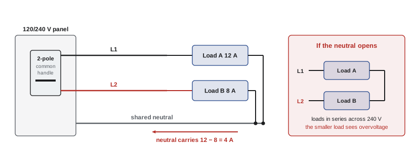
Multi-wire circuits bring three hazards, which the code addresses:
- The hot conductors must be on opposite phases (or different phases on a three-phase system). If both were on the same phase, the neutral would carry the sum of the two currents and could be overloaded without any breaker tripping.
- All ungrounded conductors must be disconnected simultaneously, by a two-pole breaker or by single-pole breakers with an identified handle tie, so that a worker who switches off one circuit does not find the shared neutral still carrying current from the other.
- The neutral must not depend on a device for continuity: it is spliced with a pigtail rather than run through the terminals of a receptacle, so that removing a receptacle cannot open the neutral and put the remaining loads in series across 240 V.
The NEC requirements for multiwire branch circuits are in 210.4: simultaneous disconnection of all ungrounded conductors, grouping of the conductors of each circuit, and limitation to line-to-neutral loads unless all ungrounded conductors are opened together.
Worked problem
Neutral current in a multi-wire circuit
A 120/240 V multi-wire branch circuit supplies 12 A on L1 and 8 A on L2, both to neutral. (a) What current flows in the neutral? (b) What if, by mistake, both hot conductors were connected to the same phase?
Show solution
- (a) On opposite phases the neutral carries the difference: \(12 - 8 = 4\) A.
- (b) On the same phase the currents add in the neutral: \(12 + 8 = 20\) A.
Answer: 4 A when connected correctly, but 20 A if both hots are on one phase. If the circuit were protected by 15 A breakers with 14 AWG conductors, the neutral would carry 20 A with no breaker to protect it: a fire hazard that is invisible to anyone checking the breakers.
Identification and labeling
Circuits must be identifiable. Every panelboard needs a legible directory showing what each circuit supplies, specific enough that a person can find the right breaker without guesswork: "Kitchen counter receptacles, east wall" rather than "Kitchen" or "Plugs". Conductors are identified by color (Lesson 2), and the conductors of each multi-wire circuit should be grouped so that their neutral can be traced.
Planning branch circuits
Good branch-circuit design goes beyond the minimum:
- Separate circuits for large or sensitive loads: refrigerators, sump pumps, freezers, network equipment and medical devices.
- Lighting and receptacles in an area on different circuits, so that a fault in one does not leave people in the dark.
- Spare capacity, both in the circuit loads and in panel spaces, for future additions.
- Voltage drop checked for long runs (Lesson 4), especially for 120 V circuits to distant outbuildings or parking areas.
Common mistakes
MistakeRating a circuit by its conductor size.
InsteadThe circuit rating is the rating of its overcurrent device.
MistakeLoading a continuous-load circuit to 100% of its breaker.
InsteadLimit continuous load to 80% of a standard device's rating.
MistakeInstalling 20 A receptacles on a 15 A circuit.
InsteadMatch receptacle ratings to the circuit rating.
MistakePutting both hot conductors of a multi-wire circuit on the same phase.
InsteadUse opposite phases and a two-pole breaker or identified handle tie.
MistakeRunning a shared neutral through receptacle terminals.
InsteadPigtail the neutral so device removal cannot open it.
Summary and key terms
- Services, feeders and branch circuits are distinguished by position in the system.
- A branch circuit's rating is its overcurrent device rating.
- Continuous loads are limited to 80% of a standard device rating.
- Receptacle ratings must match the circuit rating.
- Outlet limits or load calculations set how much one circuit may supply.
- Fixed equipment on a shared circuit is limited to 50%; cord-and-plug equipment to 80%.
- Multi-wire circuits need opposite phases, simultaneous disconnection and pigtailed neutrals.
- Branch circuit
- The conductors between the final overcurrent device and the outlets.
- Feeder
- Conductors between the service (or another source) and a distribution point.
- Service
- The conductors and equipment that bring power into a building.
- Individual branch circuit
- A branch circuit supplying only one piece of equipment.
- Continuous load
- A load at maximum current for three hours or more.
- Outlet
- A point where current is taken to supply equipment.
- Receptacle configuration
- The standardized slot pattern defining a receptacle's rating.
- Multi-wire branch circuit
- Two or more ungrounded conductors sharing one neutral.
- Handle tie
- A listed device linking breaker handles so they operate together.
- Panel directory
- The schedule identifying what each circuit supplies.
Practice problems
Work each problem on paper first, then reveal the answer to check.
A circuit is wired with 10 AWG copper but protected by a 20 A breaker. What is its rating?
Show answer
20 A.
Maximum continuous load on a 120 V, 15 A circuit?
Show answer
12 A, 1,440 W.
Maximum continuous load on a 240 V, 30 A circuit?
Show answer
24 A, 5,760 W.
Which receptacle configuration accepts both 15 A and 20 A plugs?
Show answer
5-20R.
Largest fixed appliance on a 15 A circuit that also supplies receptacles?
Show answer
7.5 A (900 W at 120 V).
Largest cord-and-plug appliance on a 15 A multi-outlet circuit?
Show answer
12 A.
Multi-wire circuit with 10 A on L1 and 10 A on L2. Neutral current?
Show answer
0 A.
Why must multi-wire circuit hots be disconnected together?
Show answer
So the shared neutral is not left carrying current from the other circuit when one is switched off.
Why pigtail the neutral of a multi-wire circuit?
Show answer
So removing a device cannot open the neutral and put loads in series across 240 V.
Give an example of a good panel directory entry.
Show answer
Kitchen counter receptacles, east wall (specific location and use).
Lesson quiz · 5 questions
Score 60% or more to complete this lesson.
Create a free account to save your progress, take quizzes and earn a certificate.