
ELEC-120 · Lesson 11 of 12 · 29 min
Class 2, communications and fire alarm circuits
Not every circuit an electrician installs carries power at 120 V or more. Thermostats, doorbells, security sensors, building automation, network cabling, Power over Ethernet devices and fire alarm systems all use low-voltage or power-limited circuits. Because their energy is limited, the code relaxes some requirements, allowing lighter cables and simpler wiring methods, but it adds others: these circuits must be kept apart from power circuits, their cables must resist the spread of fire, and fire alarm circuits must keep working when the building is burning. This lesson explains the classes of power-limited circuits, communications and data cabling, Power over Ethernet, and the special rules for fire alarm systems.
In the National Electrical Code, remote-control, signaling and power-limited circuits are covered in Chapter 7 (Articles 722, 724 and 725 for Class 1, 2 and 3 circuits), fire alarm systems in Article 760 together with NFPA 72, and communications systems in Chapter 8.
Classes of circuits
Remote-control, signaling and power-limited circuits are grouped by the energy their source can deliver:
- Class 1 circuits can carry substantial power (power-limited Class 1 sources up to 30 V and 1,000 VA, or non-power-limited up to 600 V) and are wired much like power circuits. Motor control circuits are a common example.
- Class 2 circuits are limited, by their power source, to levels considered safe from both fire and electric shock: typically not more than 30 V AC or 60 V DC and not more than 100 VA for most sources. Thermostat wiring, doorbells, most building automation, low-voltage lighting and many sensors are Class 2.
- Class 3 circuits are limited to levels safe from fire but permitting higher voltages, so they are more of a shock hazard than Class 2.
The classification depends on the source, not the wire: a circuit is Class 2 only if it is supplied by a listed Class 2 power source, such as a Class 2 transformer, power supply or control panel output, marked as such.
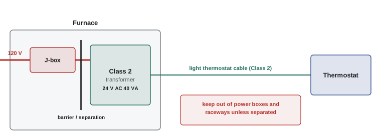
Worked problem
What a Class 2 source can deliver
A furnace control transformer is marked Class 2, 24 V AC, 40 VA. (a) What is its maximum continuous output current? (b) A Class 2 source of 24 V AC may be rated up to 100 VA; what current is that?
Show solution
- (a) \(40/24 = 1.67\) A.
- (b) \(100/24 = 4.17\) A.
Answer: 1.67 A for this transformer, and 4.17 A for the largest 24 V AC Class 2 source. The source's internal impedance or protection limits the current it can deliver even into a short circuit, which is what makes light thermostat wire safe on such circuits.
Separation from power circuits
The chief hazard for a low-voltage circuit is contact with power conductors: if a 120 V conductor faulted onto a thermostat cable, the thin wire and the devices on it could carry line voltage throughout a building, where no one expects it. The code therefore requires Class 2 and Class 3 conductors, and communications cables, to be separated from power and Class 1 conductors:
- Not in the same raceway, cable, box or enclosure, unless separated by a fixed barrier or the power conductors are only there to connect to equipment that uses both (and are kept apart within it).
- Separated by a minimum distance when run openly, unless one set is in raceway or metal-sheathed cable.
- Not strapped or tied to power conductors or raceways, or supported by them.
Worked problem
Sharing a box
An electrician wants to install a two-gang box with a 120 V switch in one side and a Class 2 occupancy sensor connection in the other. What is required?
Show solution
- Power and Class 2 conductors may share a box only if separated by a fixed barrier, or in arrangements specifically permitted.
- Use a two-gang box with a listed divider (barrier) between the sections, or separate boxes.
Answer: A box with a fixed barrier between the 120 V and Class 2 sections, or two separate boxes. Many occupancy sensors are line-voltage devices; if the sensor is Class 2, its control wiring must stay on the Class 2 side.
Communications and data cabling
Network cables (twisted-pair categories such as Cat 6 and Cat 6A), coaxial cables and optical fiber cables are installed by electricians as well as by specialized cabling technicians. The code is concerned mainly with fire spread and separation; performance standards such as ANSI/TIA-568 and ISO/IEC 11801 govern how well the cabling carries data (DCE-320).
Cables run through buildings can spread fire and smoke, so the code requires cables to be listed for the space they occupy, with tests of flame spread and smoke production:
| Space | US listing (communications) | Canadian rating |
|---|---|---|
| Plenum (air-handling space, such as above a ceiling used as a return air path) | CMP | FT6 |
| Riser (vertical shafts between floors) | CMR | FT4 |
| General purpose | CM | FT4 (FT1 for limited residential uses) |
Where communications cables enter a building from outside, they must be grounded or bonded at the entrance and protected against lightning and power-line contact by listed primary protectors, bonded to the building's grounding electrode system (Lesson 9).
Abandoned cable
Old data and low-voltage cables accumulate above ceilings as systems are replaced, adding fuel and smoke. The code requires accessible abandoned cables to be removed, or tagged for future use if they are kept.
Power over Ethernet
Power over Ethernet (PoE) sends DC power along the same twisted-pair cable that carries data, powering wireless access points, cameras, phones, sensors and even LED luminaires. The IEEE 802.3 standards define power classes: up to about 15 W at the source (802.3af), 30 W (802.3at) and 60 W or 90 W (802.3bt, using all four pairs). PoE circuits are typically Class 2 (at about 50 V to 57 V DC), so they can be installed with data cabling methods, but the current in large cable bundles generates heat.
Worked problem
Power lost in a PoE cable
A camera draws 600 mA at the end of a 90 m PoE cable powered over two pairs. Each conductor has about 0.084 Ω/m and each pair carries half the current in parallel conductors, so the loop resistance is about 7.6 Ω. Estimate the power lost in the cable.
Show solution
- Power loss: \(P = I^{2}R = 0.6^{2} \times 7.6 = 2.7\) W.
Answer: About 2.7 W, or roughly 9% of a 30 W budget. Multiply this by hundreds of cables bundled together and the heat raises cable temperatures, which is why codes and standards limit PoE currents in large bundles and why 4-pair 802.3bt powering halves the current per conductor.
The NEC (725.144) limits the current per conductor in bundles of Class 2 and Class 3 data cables carrying power, using Table 725.144, and permits higher currents for cables marked with a limited-power (LP) rating.
Fire alarm circuits
Fire alarm systems detect fires, warn occupants and summon help, and they must work during the fire itself. Their wiring therefore has requirements beyond those of other low-voltage systems:
- Fire alarm circuits are supervised: the control panel continuously monitors each circuit for opens, shorts and ground faults, reporting a trouble signal so faults are fixed before a fire.
- Circuits are identified (for example by red cable jackets or marked junction boxes) and kept separate from other systems.
- Power to the panel comes from a dedicated branch circuit, with the breaker identified and locked so it cannot be switched off accidentally, plus standby batteries.
- Survivability: in many buildings, circuits that must operate during a fire, such as those to notification appliances in high-rise buildings, must be protected by fire-rated construction or be listed circuit integrity (CI) cable.
- Installation and verification follow fire alarm standards, and systems must be inspected and tested by qualified persons before occupancy and regularly afterwards.
In the US, fire alarm systems are required by building and fire codes and designed, installed, tested and maintained to NFPA 72; NEC Article 760 covers their wiring, including power-limited fire alarm (PLFA) cables such as FPLP, FPLR and FPL.
Worked problem
Planning a fire alarm power supply
A fire alarm control panel draws 0.4 A in standby and 2.5 A in alarm. Its batteries must supply 24 hours of standby followed by 5 minutes of alarm. Estimate the battery capacity needed, adding a 20% safety factor.
Show solution
- Standby: \(0.4 \times 24 = 9.6\) Ah.
- Alarm: \(2.5 \times 5/60 = 0.21\) Ah.
- Total: \(9.81\) Ah; with 20%: \(9.81 \times 1.2 = 11.8\) Ah.
Answer: About 11.8 Ah, so a pair of 12 Ah (or larger) 12 V batteries for a 24 V panel. The required standby and alarm durations depend on the governing standard and building type; the calculation method is the same.
Other low-voltage systems
The same principles of a limited source, separation and fire-rated cabling apply to other systems an electrician meets: intrusion alarms, access control, nurse call, sound and public address systems, and low-voltage lighting. Audio amplifiers can produce Class 2 or Class 3 outputs depending on their power, and their speaker wiring must match the class marked on the amplifier. Low-voltage landscape lighting uses listed Class 2 or similar power units, often with GFCI protection on the supply receptacle outdoors.
Building automation and control systems increasingly combine power and data: a single cable can carry Ethernet and power to a sensor, a damper actuator or a luminaire. This blurs the line between the electrician's and the cabling technician's work, so electricians need to know both the code rules for the circuit class and the performance requirements of the cabling standards. Labeling each cable at both ends, recording it in a schedule and leaving service loops make these systems far easier to maintain.
Common mistakes
MistakeCalling a circuit Class 2 because its wire is thin.
InsteadClass 2 is defined by a listed, marked power-limited source.
MistakeRunning Class 2 or data cable in the same box or raceway as power without a barrier.
InsteadSeparate them with barriers, distance or separate enclosures.
MistakeInstalling general-purpose cable in a plenum.
InsteadUse plenum-rated cable (CMP or FT6) in air-handling spaces.
MistakeLeaving abandoned cable above ceilings.
InsteadRemove accessible abandoned cable or tag it for future use.
MistakeFeeding a fire alarm panel from a shared, unmarked circuit.
InsteadUse a dedicated, identified and locked circuit with standby batteries.
Summary and key terms
- Class 1, 2 and 3 circuits are defined by their power sources; Class 2 is safe from fire and shock.
- Class 2 sources are typically limited to 30 V AC or 60 V DC and 100 VA.
- Low-voltage and communications cables must be separated from power conductors.
- Cables must be listed for plenum, riser or general spaces; abandoned cable must be removed.
- PoE powers devices over data cables; bundle heating limits current.
- Fire alarm circuits are supervised, dedicated, identified and, where required, survivable.
- Class 1 circuit
- A remote-control or signaling circuit wired much like power wiring.
- Class 2 circuit
- A circuit limited by its source to levels safe from fire and shock.
- Class 3 circuit
- A power-limited circuit safe from fire but with higher voltage than Class 2.
- Power-limited source
- A listed transformer or supply whose output cannot exceed set limits.
- Plenum
- An air-handling space, such as a ceiling used as a return air path.
- Riser
- A vertical shaft or path between floors.
- Power over Ethernet
- Delivering DC power over twisted-pair data cable.
- Supervision
- Continuous monitoring of fire alarm circuits for faults.
- Circuit integrity cable
- Cable that keeps operating for a rated time in a fire.
- Abandoned cable
- Installed cable that is not terminated and not tagged for future use.
Practice problems
Work each problem on paper first, then reveal the answer to check.
What defines a Class 2 circuit?
Show answer
A listed Class 2 power source.
Maximum output current of a 24 V, 75 VA Class 2 transformer?
Show answer
3.1 A.
Name three Class 2 applications.
Show answer
Thermostats, doorbells, building automation (also sensors, low-voltage lighting).
Why separate Class 2 from power conductors?
Show answer
A fault could put line voltage on low-voltage wiring throughout a building.
Cable rating for a return-air ceiling plenum in Canada? In the US?
Show answer
FT6; CMP.
May CMP cable be used in a riser?
Show answer
Yes; higher ratings may replace lower ones.
What must be done with accessible abandoned data cable?
Show answer
Remove it or tag it for future use.
PoE loss with 0.4 A and 10 Ω loop resistance?
Show answer
1.6 W.
What is fire alarm supervision?
Show answer
Continuous monitoring for opens, shorts and ground faults.
Standby 0.25 A for 24 h, alarm 2 A for 5 min, +20%. Battery?
Show answer
(6 + 0.17) × 1.2 ≈ 7.4 Ah.
Lesson quiz · 5 questions
Score 60% or more to complete this lesson.
Create a free account to save your progress, take quizzes and earn a certificate.