
CIV-224 · Lesson 9 of 12 · 22 min
Moving loads: crane wheels and design trucks
Influence lines tell you where to put one load or a uniform load. Real moving loads come in groups: the two wheels of a crane end truck, the axles of a design truck, the bogies of a train. The group moves as a unit, with fixed spacings, so the question becomes where to place the whole group to produce the largest moment or shear. This lesson develops the rules for that placement and applies them to the garage's crane runway beams and to the access road bridge, using the design vehicles specified by the bridge code.
A series of point loads and an influence line
For a quantity with a known influence line, the effect of a group of point loads \(P_i\) at positions where the ordinates are \(\eta_i\) is \(\sum P_i \eta_i\). To maximize it, move the group across the structure and evaluate the sum. Because influence lines for determinate structures are made of straight segments, the maximum always occurs with one of the loads at a peak or kink of the influence line. So you only need to try placing each load in turn at the peak, which turns an infinite search into a handful of trials.
For the moment at a fixed section C of a simple beam, this means placing each load at C in turn and computing \(\sum P_i \eta_i\). A useful test tells you which placement wins without computing them all: moving the group a small distance to the left changes the moment at C by an amount proportional to (load on the left part)/a minus (load on the right part)/b. The maximum occurs when moving a load across C changes the sign of this quantity, which happens when the average load per unit length on each side of C is about the same.
The absolute maximum moment in a simple span
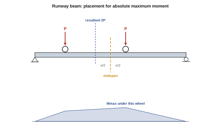
For a beam, the more important question is often the absolute maximum moment: the largest moment anywhere in the span for any position of the group. The moment under a particular load is greatest when that load and the resultant of all the loads on the span are placed equidistant from midspan. The absolute maximum usually occurs under the load nearest the resultant, typically one of the heavier loads, with that load and the resultant symmetric about the center line.
The rule follows from a short derivation. Let the resultant R of the loads on the span lie a distance e to the right of the load being considered, and let that load be at x from A. The moment under it is \(M = R(L - x - e)x/L - M_{\text{left}}\), where \(M_{\text{left}}\) is the moment of the loads to its left about it, which does not depend on x as long as the same loads stay on the span. Setting \(dM/dx = 0\) gives \(x = (L - e)/2\): the load is \(e/2\) left of midspan and the resultant \(e/2\) right of it.
Crane runway beams
A bridge crane rides on two runway beams, one along each side of the building. Each end truck of the crane has two wheels at a fixed spacing, the wheelbase, and as the crane travels, the wheel pair rolls along the runway beam. The wheel loads depend on the crane's weight, the lifted load and where the trolley is; they are largest on one side when the trolley carrying the hook is pulled all the way over to that side. Codes also require an allowance for impact and for horizontal surge and braking forces.
Worked problem
Maximum moment in a runway beam
The garage's runway beams span 25 ft between columns, simply supported. Each end truck has two wheels 10 ft apart, each delivering a factored load of 9 kips including impact. Find the absolute maximum moment and compare it with the moment when the wheels are placed symmetrically about midspan.
Show solution
- The resultant of the two wheels is 18 kips at their midpoint, 5 ft from each wheel, so \(e = 5\ \text{ft}\).
- Place one wheel \(e/2 = 2.5\ \text{ft}\) to the right of midspan, at 15 ft from A, and the resultant 2.5 ft to the left; the other wheel is then at 5 ft from A.
- Reaction at B: \(R_B = 9(15 + 5)/25 = 7.2\ \text{kips}\).
- \[M_{\max} = R_B(25 - 15) = 7.2 \times 10 = 72.0\ \text{kip·ft}\]
- Symmetric placement (wheels at 7.5 ft and 17.5 ft): \(R = 9\ \text{kips}\) and \(M = 9 \times 7.5 = 67.5\ \text{kip·ft}\) under each wheel.
- One wheel alone at midspan: \(9 \times 25/4 = 56.3\ \text{kip·ft}\).
Answer: The absolute maximum is 72.0 kip·ft under the wheel 2.5 ft right of midspan, about 7 percent more than the symmetric placement. If the wheelbase were long compared with the span (more than about 0.586L), a single wheel at midspan would govern, because the second wheel would then be off the beam or near a support.
Maximum shear
The maximum end shear (the reaction) in a simple span occurs with the heaviest group of loads as close as possible to that support, usually with the leading heavy axle just at the support. Shear at an interior section follows the shear influence line: move the group onto the span from the far end, with a heavy load just to the right of the section, and check whether adding the next load beyond the section increases or decreases the shear. For crane runways, the maximum reaction also gives the vertical load on the column bracket, and the end shear governs the beam's bearing and web design.
Highway design vehicles
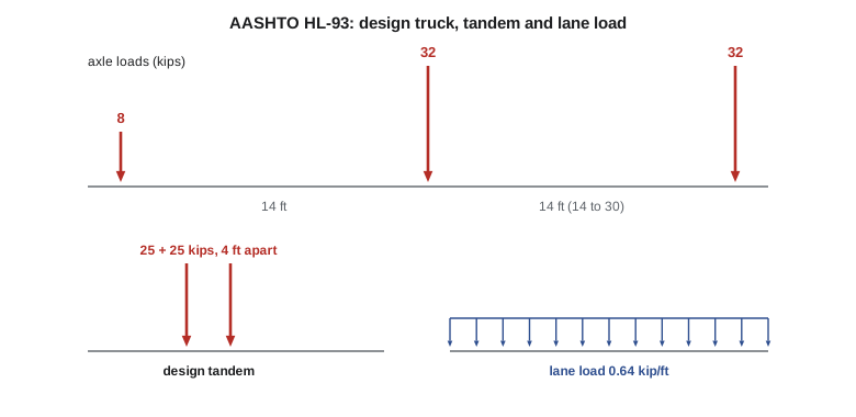
Highway bridges in the United States are designed to the AASHTO LRFD Bridge Design Specifications. Its standard live load is HL-93, which combines a vehicle and a lane load. The vehicle is either the design truck, with axles of 8, 32 and 32 kips spaced 14 ft and a variable 14 to 30 ft apart (the spacing that produces the greatest effect is used), or the design tandem, two 25-kip axles 4 ft apart, whichever governs. The lane load is 0.64 kip/ft applied over the lengths that produce the extreme effect. The truck (or tandem) and the lane load are applied together in each design lane.
Dynamic effects are covered by a dynamic load allowance, 33 percent for most components, applied to the design truck or tandem but not to the lane load. Load factors, multiple presence factors and the distribution of lane loads among girders are covered in bridge design courses.
Worked problem
The truck on the access road bridge
For the 60 ft access road span, find the maximum moment due to one HL-93 design truck with the 14 ft rear spacing, placing the axles according to the absolute maximum rule.
Show solution
- Total \(R = 72\ \text{kips}\). With axle positions 0, 14 and 28 ft from the 8-kip front axle, the resultant is at \((32 \times 14 + 32 \times 28)/72 = 18.67\ \text{ft}\) behind the front axle.
- The middle 32-kip axle is at 14 ft, so \(e = 18.67 - 14 = 4.67\ \text{ft}\). Place it \(e/2 = 2.33\ \text{ft}\) ahead of midspan, at 32.33 ft from the trailing support, with the resultant 2.33 ft behind midspan.
- Axle positions from the trailing support: rear 32 kips at 18.33 ft, middle 32 kips at 32.33 ft, front 8 kips at 46.33 ft. Reaction at the trailing support: \(R = 72(60 - 27.67)/60 = 38.8\ \text{kips}\), since the resultant is at 27.67 ft.
- \[M = 38.8(32.33) - 32(32.33 - 18.33) = 1254 - 448 = 806\ \text{kip·ft}\]
Answer: The design truck alone produces about 806 kip·ft. Adding the lane load (\(0.64 \times 60^2/8 = 288\ \text{kip·ft}\)) and the dynamic allowance on the truck gives \(1.33(806) + 288 = 1360\ \text{kip·ft}\) per lane before load factors and distribution. The program below confirms the truck result by brute force.
The design tandem must also be checked, because it governs for short spans. On the 60 ft span its two 25-kip axles have their resultant midway between them, 2 ft from each, so the critical axle goes 1 ft past midspan, at 31 ft from the trailing support, with the other axle at 27 ft. The reaction is \(50(60 - 29)/60 = 25.8\ \text{kips}\) and the moment under the critical axle is \(25.8(31) - 25(4) = 701\ \text{kip·ft}\), less than the truck's 806 kip·ft. For spans below roughly 40 ft the tandem usually wins. The variable rear spacing of the truck is set to 14 ft for maximum moment in simple spans, but the longer 30 ft spacing can govern negative moment over interior supports of continuous girders, where the two heavy axles straddle the support.
Whatever the vehicle, the procedure is the same: identify the influence line, try each heavy axle at the critical point, check whether axles leave or enter the span, and keep the largest result. A spreadsheet or short program removes the bookkeeping errors that make hand calculations of multi-axle trucks error-prone.
Moving a load train by computer
Sofia's program moves the design vehicle across the span in 10 mm steps, in both directions, and records the largest moment under any axle and the largest end reaction. It then combines the truck with the lane load and applies the dynamic allowance.
# Move a train of axles across a simple span and record the worst moment and end shear
L = 60.0
axles = [8.0, 32.0, 32.0]                     # loads
gaps = [14.0, 14.0]                       # spacing between consecutive axles
pos = [0.0]
for g in gaps: pos.append(pos[-1] + g)
train = list(zip(pos, axles))     # offsets from the front axle

def effects(front):
    on = [(front - d, P) for d, P in train if 0.0 <= front - d <= L]
    RA = sum(P * (L - x) for x, P in on) / L
    best = 0.0
    for x, _ in on:               # moment peaks under an axle
        m = RA * x - sum(P * (x - xi) for xi, P in on if xi < x)
        best = max(best, m)
    return best, RA

step = 0.01
n = int((L + pos[-1]) / step) + 1
Mmax = max(effects(i * step)[0] for i in range(n))
Vmax = max(effects(i * step)[1] for i in range(n))
# also run the truck reversed, since it may travel either way
train = [(pos[-1] - d, P) for d, P in train]
Mmax = max(Mmax, max(effects(i * step)[0] for i in range(n)))
Vmax = max(Vmax, max(effects(i * step)[1] for i in range(n)))
lane = 0.64
M_lane = 1.0 * Mmax + lane * L ** 2 / 8
V_lane = 1.0 * Vmax + lane * L / 2
print(f"Truck alone: Mmax = {Mmax:.0f} kip*ft, end shear = {Vmax:.0f} kips")
print(f"Lane load:   Mmax = {M_lane:.0f} kip*ft, end shear = {V_lane:.0f} kips")
print(f"Truck with dynamic allowance {0.33:.2f}: Mmax = {(1 + 0.33) * Mmax:.0f} kip*ft")Truck alone: Mmax = 807 kip*ft, end shear = 61 kips Lane load: Mmax = 1095 kip*ft, end shear = 80 kips Truck with dynamic allowance 0.33: Mmax = 1073 kip*ft
Note that in AASHTO the truck and lane load act together, so the program's lane line adds the full truck effect to the uniform 0.64 kip/ft; the dynamic allowance applies to the truck part only.
Common mistakes
MistakePlacing the heaviest axle at midspan and stopping.
InsteadPlace the critical axle and the resultant equidistant from midspan, and check the other heavy axles.
MistakeForgetting that axles move off the span as the vehicle shifts.
InsteadRecompute the resultant whenever an axle leaves or enters the span.
MistakeApplying the dynamic load allowance to the uniform lane load.
InsteadIt applies to the truck axles only.
MistakeRunning the truck in only one direction.
InsteadVehicles travel both ways; asymmetric trucks give different results reversed.
Summary and key terms
- For a group of moving loads, the maximum effect occurs with one load at a peak of the influence line; try each heavy load there.
- Absolute maximum moment in a simple span: the critical load and the resultant are equidistant from midspan.
- Maximum end shear: heaviest loads as close as possible to the support.
- Crane runway beams carry pairs of wheel loads with impact, surge and braking forces.
- AASHTO uses HL-93: the design truck (8, 32, 32 kips) or tandem (2 × 25 kips) plus a 0.64 kip/ft lane load.
- The dynamic load allowance increases the truck axle loads but not the uniform lane load.
- Wheelbase
- The spacing between the wheels of a crane end truck or a vehicle.
- Absolute maximum moment
- The largest moment anywhere in a member for any position of a moving load group.
- Design truck
- A code-specified vehicle used to represent highway live load.
- Lane load
- A code-specified uniform load, sometimes with axles, representing a line of traffic.
- Dynamic load allowance
- An increase in vehicle loads to account for dynamic effects.
- Runway beam
- A beam carrying the wheels of a bridge crane along a building.
- Surge force
- A horizontal force on a crane runway from trolley acceleration and braking.
- Resultant
- The single force equivalent to a group of loads, located at their centroid.
Practice problems
Work each problem on paper first, then reveal the answer to check.
Two wheels of 12 kips each, 6 ft apart, cross a 30 ft simple span. Find the absolute maximum moment.
Show answer
Wheel at 16.5 ft: \(R_B = 12(16.5 + 10.5)/30 = 10.8\); \(M = 10.8 \times 13.5 = 145.8\ \text{kip·ft}\).
Where should a group of loads be placed for maximum end shear?
Show answer
With the heavy loads as close to that support as possible, usually the leading heavy axle at the support.
Why does the absolute maximum moment not occur at midspan for two equal wheels?
Show answer
The moment under a wheel is maximized when the wheel and the resultant are symmetric about midspan, which puts the wheel off center.
What are the axle loads of the HL-93 design truck and the design tandem?
Show answer
Truck: 8, 32 and 32 kips; tandem: two 25-kip axles 4 ft apart.
Is the dynamic load allowance applied to the uniform lane load?
Show answer
No, only to the truck axles.
When might a single wheel at midspan govern over the two-wheel placement?
Show answer
When the wheelbase is long relative to the span, roughly over 0.586L.
Lesson quiz · 5 questions
Score 60% or more to complete this lesson.
Create a free account to save your progress, take quizzes and earn a certificate.