
CIV-224 · Lesson 11 of 12 · 29 min
Deflections by virtual work
The moment-area method works well for beams, but it does not extend easily to trusses, frames with several members or deflections in a direction other than vertical. The method of virtual work does all of these with one procedure. It is the most versatile hand method for displacements, it is the foundation of the force method for indeterminate structures in lesson 12, and its ideas underlie the finite element method. The core idea is simple: to find a displacement at a point, apply an imaginary unit load at that point in the direction of the displacement, and use the work it would do.
Work and the principle of virtual work
A force does work when its point of application moves in the direction of the force: work equals force times the displacement component along it. For a linearly elastic structure loaded gradually, the external work done by the loads is stored as strain energy in the members. Virtual work separates the forces from the displacements. It considers one system of forces in equilibrium and an unrelated set of compatible displacements, and states that if the displacements are imposed on the structure while the forces stay constant, the external virtual work equals the internal virtual work.
For computing deflections we use the principle of virtual forces. The virtual force system is a unit load (or unit couple) applied at the point and in the direction of the displacement we want, together with the internal forces and reactions it produces. The real displacements are those caused by the actual loads, temperature changes or other effects. Equating external and internal virtual work gives
where n is the internal force in a member due to the unit load and \(d\delta\) is the real deformation of an element of that member. The left side is the work of the unit load moving through the real displacement \(\Delta\); the right side is the work of the virtual internal forces moving through the real internal deformations. Because the unit load and the real loads are independent, the same real deformation can be paired with any virtual load to give any displacement.
Trusses
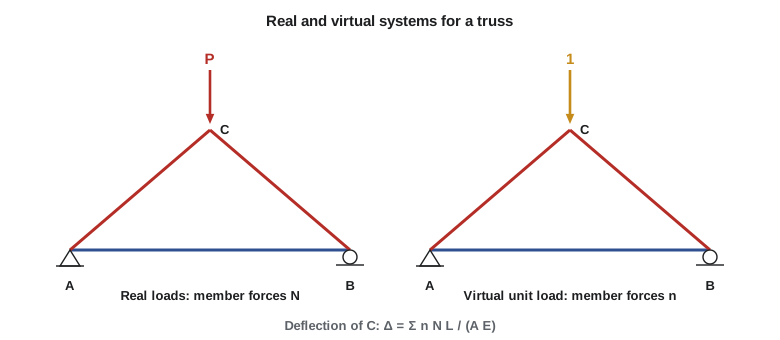
In a truss, each member has a constant axial force N from the real loads, and its real elongation is \(NL/(AE)\). If n is the force in the same member due to a unit load at the joint and in the direction of the desired displacement, then
summed over all members. Use a consistent sign convention, tension positive for both n and N, and the sign of \(\Delta\) tells you whether the joint moves in the direction of the unit load (positive) or opposite to it. Organizing the calculation as a table with columns for L, A, N, n and the product \(nNL/A\) keeps it tidy, and a spreadsheet or short program makes it painless for large trusses.
The same formula handles deformations that do not come from loads. If a member's length changes by \(\delta_{\text{other}}\), because of a temperature change (\(\alpha\,\Delta T\,L\)) or a fabrication error, the displacement is \(\Delta = \sum n\,\delta_{\text{other}}\). Engineers use this to camber trusses: by making some members slightly longer or shorter on purpose, they build the truss with an upward deflection that cancels the dead load deflection.
Worked problem
Deflection of a simple roof truss
A triangular truss over the salt shed's entry has a pin at A, a roller at B 24 ft away, and an apex C 9 ft above the midpoint of AB. A nominal load of 27 kips hangs from C. The inclined members AC and BC have \(A = 4.5\ \text{in.}^2\) and the tie AB has \(A = 3.0\ \text{in.}^2\); \(E = 29{,}000\ \text{ksi}\). Find the vertical deflection of C and the horizontal movement of the roller B.
Show solution
- Geometry: AC = BC = \(\sqrt{12^2 + 9^2} = 15\ \text{ft}\). Real forces: each reaction is 13.5 kips; at A, the vertical component of AC is 13.5 kips, so \(N_{AC} = -13.5(15/9) = -22.5\ \text{kips}\), and \(N_{AB} = 22.5(12/15) = +18.0\ \text{kips}\). By symmetry \(N_{BC} = -22.5\ \text{kips}\).
- Virtual forces for a unit load down at C: the same pattern divided by 27, so \(n_{AC} = n_{BC} = -0.833\) and \(n_{AB} = +0.667\).
- \[\Delta_C = \frac{2(-0.833)(-22.5)(180)}{4.5(29\,000)} + \frac{(0.667)(18.0)(288)}{3.0(29\,000)} = 0.052 + 0.040 = 0.092\ \text{in.}\]
- Horizontal movement of B: apply a unit horizontal load at B. It is resisted by the pin at A through the tie alone, so \(n_{AB} = 1\) and the others are zero: \(\Delta_B = 1(18.0)(288)/(3.0 \times 29\,000) = 0.060\ \text{in.}\), outward.
Answer: C drops 0.092 in. and B slides 0.060 in. outward. If the tie were also heated 50 °F (\(\alpha = 6.5 \times 10^{-6}\)/°F), its free elongation of \(6.5 \times 10^{-6} \times 50 \times 288 = 0.094\ \text{in.}\) would add \(0.667 \times 0.094 = 0.063\ \text{in.}\) to the drop at C, a reminder that temperature can matter as much as load.
Beams and frames
In a beam, the dominant real deformation is bending. An element of length dx rotates through \(d\theta = M\,dx/(EI)\) under the real moment M, and the virtual moment m from the unit load does work \(m\,d\theta\) on it. Hence
where for a slope you apply a unit couple at the point and \(m_\theta\) is its moment diagram. For a frame, sum the integrals over all members. Axial and shear deformations contribute too, with terms \(\int nN/(AE)\,dx\) and \(\int f_s vV/(GA)\,dx\), but for ordinary beams and frames they are small compared with bending and are usually neglected. For trusses, by contrast, the axial term is everything.
You must use the same sign convention for m and M in each member, and the same coordinate x. Choose the origin for each segment wherever the expressions are simplest, often at a free end or a support, and you can choose differently for different segments, as long as m and M in that segment are both written with the same origin.
Worked problem
Slope at the support of a simply supported beam
Find the end slope of a simply supported beam of span L and constant EI under a uniform load w.
Show solution
- Real moment: \(M = wx(L - x)/2\).
- Virtual system: a unit couple at the left end A. Its moment diagram falls linearly from 1 at A to 0 at B: \(m_\theta = 1 - x/L\).
- \[EI\,\theta_A = \int_0^L \Big(1 - \frac{x}{L}\Big)\frac{wx(L - x)}{2}\,dx = \frac{w}{2}\int_0^L \frac{x(L - x)^2}{L}\,dx = \frac{w}{2}\cdot\frac{L^3}{12} = \frac{wL^3}{24}\]
Answer: \(\theta_A = wL^3/(24EI)\), the same as the conjugate beam reaction in lesson 10.
Worked problem
Tip deflection of the canopy overhang
Find the vertical deflection of the tip C of the canopy beam (pin A, roller B 20 ft away, overhang BC 6 ft) under a nominal uniform load of 0.48 kip/ft with \(EI = 60\,400\ \text{kip·ft}^2\), and compare with the numerical result of lesson 10.
Show solution
- Real reactions: \(R_B = 0.48(26)(13)/20 = 8.11\ \text{kips}\), \(R_A = 4.37\ \text{kips}\). In AB (x from A): \(M = 4.37x - 0.24x^2\). In the overhang (s from C): \(M = -0.24s^2\).
- Virtual unit load down at C: reactions \(-0.3\) at A (downward) and \(1.3\) at B. In AB: \(m = -0.3x\). In the overhang: \(m = -s\).
- \[EI\,\Delta_C = \int_0^{20} (-0.3x)(4.37x - 0.24x^2)\,dx + \int_0^6 (-s)(-0.24s^2)\,ds = -614 + 78 = -536\]
- \[\Delta_C = -\frac{536}{60\,400} = -0.0089\ \text{ft} = -0.107\ \text{in.}\]
Answer: The negative sign means the tip moves opposite to the unit load, that is, 0.107 in. upward, exactly matching the numerical integration in lesson 10.
Product integrals
Because m and M are usually simple shapes (rectangles, triangles, parabolas), the integral of their product over a member of length L can be read from a table instead of integrated each time. With a and b the end or peak values of the two diagrams:
| m diagram | M diagram | ∫ m M dx |
|---|---|---|
| Rectangle a | Rectangle b | abL |
| Rectangle a | Triangle, 0 to b | abL/2 |
| Triangle, 0 to a | Triangle, 0 to b (same direction) | abL/3 |
| Triangle, 0 to a | Triangle, b to 0 (opposite direction) | abL/6 |
| Rectangle a | Parabola, peak b at midspan (uniform load) | 2abL/3 |
| Triangle, 0 to a | Parabola, peak b at midspan | abL/3 |
Divide the result by EI for each member and add. For frames with several members this turns a page of integration into a few lines, and it is how most engineers do virtual work by hand.
Worked problem
Sway of the portal frame on a roller
For the portal frame of lesson 6 (columns 14 ft, beam 20 ft, pin at A, roller at D, uniform load 1.2 kip/ft on the beam and 2.5 kips horizontal at B), find the horizontal movement of the roller D, taking \(EI = 161\,000\ \text{kip·ft}^2\) for all members and treating the loads as specified for illustration.
Show solution
- Real moments (tension inside positive): column AB \(M = 2.5y\); beam \(M = 35 + 10.25x - 0.6x^2\); column DC \(M = 0\).
- Virtual system: a unit horizontal load at D, to the right. The reactions are a unit horizontal force at A to the left and no vertical forces. Then column AB has \(m = y\), the beam has \(m = 14\) throughout, and column DC has \(m = y\) measured up from D.
- Column AB, triangle times triangle in the same direction: \(\tfrac{1}{3}(14)(35)(14) = 2287\).
- Beam: \(14 \int_0^{20} (35 + 10.25x - 0.6x^2)\,dx = 14(700 + 2050 - 1600) = 16\,100\).
- \[\Delta_D = \frac{2287 + 16\,100}{161\,000} = 0.114\ \text{ft} = 1.37\ \text{in.}\]
Answer: The roller slides 1.37 in. outward, about 1/120 of the column height. Most of it comes from the beam bending under gravity load and spreading the column bases. This is one reason real portal frames have both bases pinned or fixed: the extra restraint makes the frame indeterminate but far stiffer.
Truss deflection by computer
Sofia applies the unit load method to the whole garage Pratt truss under specified dead plus snow load, using trial member areas. The program reuses the joint-equilibrium solver from lesson 4 twice, once for the real loads and once for a unit load at midspan, and sums \(nNL/(AE)\). It also reports which members contribute most, which tells the designer where extra area would reduce deflection most efficiently.
import math

def solve(A, b):
    n = len(b); M = [row[:] + [b[i]] for i, row in enumerate(A)]
    for k in range(n):
        p = max(range(k, n), key=lambda i: abs(M[i][k])); M[k], M[p] = M[p], M[k]
        for i in range(k + 1, n):
            f = M[i][k] / M[k][k]
            for jj in range(k, n + 1): M[i][jj] -= f * M[k][jj]
    x = [0.0] * n
    for i in reversed(range(n)):
        x[i] = (M[i][n] - sum(M[i][jj] * x[jj] for jj in range(i + 1, n))) / M[i][i]
    return x

span, panels, depth = 60.0, 6, 7.0
a = span / panels
nodes = {}
for i in range(panels + 1):
    nodes[f"L{i}"] = (i * a, 0.0); nodes[f"U{i}"] = (i * a, depth)
mem = [(f"L{i}", f"L{i+1}") for i in range(panels)] + [(f"U{i}", f"U{i+1}") for i in range(panels)]
mem += [(f"L{i}", f"U{i}") for i in range(panels + 1)]
mem += [(f"U{i}", f"L{i+1}") for i in range(panels // 2)] + [(f"U{i+1}", f"L{i}") for i in range(panels // 2, panels)]
area = {m: (9.0 / 144 if m[0][0] == m[1][0] else 4.5 / 144) for m in mem}   # chords vs webs
E = 29000.0 * 144
sup = [("L0", 0), ("L0", 1), (f"L{panels}", 1)]
names = list(nodes); idx = {n: k for k, n in enumerate(names)}

def member_forces(loads):
    nu = len(mem) + len(sup)
    A = [[0.0] * nu for _ in range(2 * len(names))]; rhs = [0.0] * (2 * len(names))
    for m, (i, j) in enumerate(mem):
        (xi, yi), (xj, yj) = nodes[i], nodes[j]
        L = math.hypot(xj - xi, yj - yi); c, s = (xj - xi) / L, (yj - yi) / L
        A[2*idx[i]][m] += c; A[2*idx[i]+1][m] += s; A[2*idx[j]][m] -= c; A[2*idx[j]+1][m] -= s
    for k, (n, d) in enumerate(sup):
        A[2*idx[n] + d][len(mem) + k] = 1.0
    for n, fy in loads.items():
        rhs[2*idx[n] + 1] -= fy
    return solve(A, rhs)[:len(mem)]

P = 15.7
real = member_forces({f"U{i}": -P * (0.5 if i in (0, panels) else 1.0) for i in range(panels + 1)})
unit = member_forces({"L3": -1.0})                      # unit load down at midspan bottom joint
total = 0.0
for (i, j), N, n in zip(mem, real, unit):
    (xi, yi), (xj, yj) = nodes[i], nodes[j]
    L = math.hypot(xj - xi, yj - yi)
    total += n * N * L / (area[(i, j)] * E)
print(f"Midspan deflection under specified load: {total * 12:.2f} in. (span/{span / total:.0f})")
top = sorted(((abs(n * N * math.hypot(nodes[j][0]-nodes[i][0], nodes[j][1]-nodes[i][1]) / (area[(i, j)] * E)), i + j)
              for (i, j), N, n in zip(mem, real, unit)), reverse=True)[:4]
print("Largest contributions:", ", ".join(f"{name} {v / total * 100:.0f}%" for v, name in top))Midspan deflection under specified load: 0.82 in. (span/878) Largest contributions: U3U4 12%, U2U3 12%, U6L5 8%, U0L1 8%
The chords dominate the total, so increasing the chord areas reduces deflection most. The specified-load deflection is a small fraction of the span, well within the usual roof limits, but the truss will still be fabricated with a camber equal to its dead load deflection so that the roof is flat once the roofing is installed.
Common mistakes
MistakeUsing different sign conventions for n and N, or for m and M.
InsteadTension positive in trusses; the same moment convention and origin for m and M in each segment.
MistakeApplying the unit load in the wrong direction or at the wrong joint.
InsteadApply it at the point and in the direction of the displacement you want; a negative result means the opposite direction.
MistakeForgetting members with zero real force but nonzero virtual force, or vice versa.
InsteadTheir products are zero, but check every member in the table so none is missed.
MistakeUsing factored loads for serviceability deflections.
InsteadUse specified loads for serviceability checks.
Summary and key terms
- Virtual work: external virtual work of a unit load equals internal virtual work on the real deformations.
- Trusses: \(\Delta = \sum nNL/(AE)\); temperature and fabrication errors: \(\Delta = \sum n\,\delta\).
- Beams and frames: \(\Delta = \int mM/(EI)\,dx\), summed over members; use a unit couple for rotation.
- Axial and shear deformation are usually negligible in beams and frames.
- Product integral tables replace integration for standard diagram shapes.
- A negative result means the displacement is opposite to the assumed unit load direction.
- Virtual work
- Work done by real forces through virtual displacements, or virtual forces through real displacements.
- Unit load method
- A displacement calculation using a unit load at the point and direction of interest.
- Virtual force system
- A unit load or couple and the internal forces and reactions it produces.
- Product integral
- The integral of the product of two moment diagrams over a member, read from a table.
- Camber
- An upward curvature built into a member or truss to offset its dead load deflection.
- Strain energy
- Energy stored in a deformed elastic structure.
- Compatible displacements
- Displacements consistent with the supports and continuity of the structure.
- Unit couple
- A virtual moment of magnitude one, used to find a rotation.
Practice problems
Work each problem on paper first, then reveal the answer to check.
A truss member 12 ft long with \(A = 4\ \text{in.}^2\) carries N = 30 kips and n = 0.6. What is its contribution to \(\Delta\) (E = 29,000 ksi)?
Show answer
\(0.6(30)(144)/(4 \times 29\,000) = 0.022\ \text{in.}\)
What virtual load do you apply to find the rotation at a point?
Show answer
A unit couple at that point.
Evaluate \(\int mM\,dx\) for a rectangle of height 2 and a triangle from 0 to 30 over 5 m.
Show answer
\(abL/2 = 2 \times 30 \times 5/2 = 150\).
How would you find the deflection caused by heating one truss member?
Show answer
\(\Delta = n\,\alpha\,\Delta T\,L\) for that member, using its virtual force n.
Why can axial deformation usually be neglected in beams?
Show answer
Bending deformations are much larger for members whose span greatly exceeds their depth.
What does a negative result from the unit load method mean?
Show answer
The displacement is opposite in direction to the applied unit load.
Lesson quiz · 5 questions
Score 60% or more to complete this lesson.
Create a free account to save your progress, take quizzes and earn a certificate.