
CIV-224 · Lesson 6 of 12 · 26 min
Determinate frames: axial force, shear and moment
A frame is a structure whose members are joined by at least some rigid connections, so that members carry bending moment, shear and axial force together. Portal frames for garages and warehouses, rigid bents in buildings of several stories, sign structures and crane brackets are all frames. Most real frames are statically indeterminate, but determinate frames are common enough in their own right (three-hinged portals, cantilever brackets, frames on a pin and a roller) and they are the building blocks for the indeterminate methods of later courses. The skills in this lesson, drawing free bodies of members and joints and plotting internal forces around corners, carry straight over.
From beams to frames
A frame member is analyzed exactly like a beam once you know the forces acting on its ends. The difference is that frames turn corners. At a rigid joint, the end moment of one member passes into the next, and the shear of one member becomes axial force in the other when they meet at a right angle. Tracking these transfers is the whole art. The procedure is reliable if you follow it step by step.
- Check stability and determinacy, and find the support reactions from equilibrium of the whole frame, plus any equations of condition at hinges.
- Cut each member free of its joints, and draw its free-body diagram with the end forces (axial, shear, moment) acting on it. Forces on the two sides of a joint are equal and opposite.
- Work from a support, where the end forces are known from the reactions, around the frame member by member. At each rigid joint, use joint equilibrium to pass the moment, and to convert the shear and axial force of one member into the axial force and shear of the next.
- Draw the axial, shear and moment diagrams for each member along its own axis, and check that every joint is in equilibrium.
Sign conventions for frames
Because members point in different directions, a positive sign for shear or moment depends on which side you look from. Two practical conventions avoid the confusion. For axial force, tension is positive, which needs no reference direction. For moment, structural engineers usually draw the moment diagram on the tension side of each member, and label it with a magnitude only. A moment diagram plotted on the outside of a column at the knee of a portal means tension on the outside face there, which immediately tells a concrete designer where the reinforcement goes and a steel designer which flange is in compression. For shear, pick a direction along each member (for example, viewing each column from the inside of the frame) and stick to it.
Worked problem
A portal frame on a pin and a roller
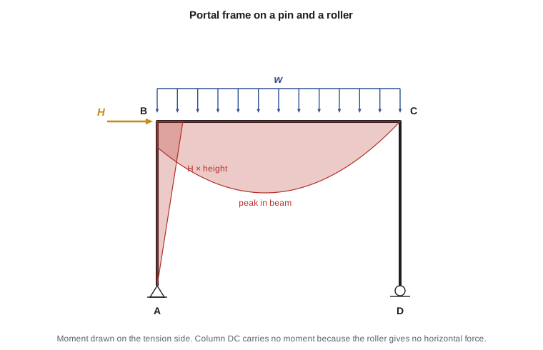
A small frame supports the garage's mezzanine edge. It has columns AB and DC, each 14 ft high, and a beam BC 20 ft long with rigid joints at B and C. The base A is pinned and the base D sits on a roller. The beam carries a factored uniform load of 1.2 kip/ft, and a factored horizontal load of 2.5 kips acts to the right at B. Find the reactions and draw the moment diagram.
Show solution
- Reactions. Horizontal: \(A_x = 2.5\ \text{kips}\) to the left. Moments about A: \(20D_y - 24(10) - 2.5(14) = 0\), so \(D_y = 13.75\ \text{kips}\). Vertical: \(A_y = 24 - 13.75 = 10.25\ \text{kips}\).
- Column AB carries an axial compression of 10.25 kips and a constant shear of 2.5 kips. Its moment grows linearly from zero at the pin A to \(2.5 \times 14 = 35\ \text{kip·ft}\) at B, with tension on the inside face.
- Column DC carries only the vertical reaction, 13.75 kips in compression, and no moment, because the roller provides no horizontal force.
- Beam BC: at B, joint equilibrium passes the 35 kip·ft moment into the beam, and the column's axial force becomes the beam's end shear, 10.25 kips. The horizontal forces at B cancel, so the beam has no axial force. With x measured from B,
- \[M(x) = 35 + 10.25x - 0.6x^2\]
- At C, \(M = 35 + 205 - 240 = 0\), consistent with the moment-free column DC. The peak is at \(x = 10.25/1.2 = 8.54\ \text{ft}\): \(M_{\max} = 35 + 87.6 - 43.8 = 78.8\ \text{kip·ft}\).
Answer: Reactions \(A_x = 2.5\) kips left, \(A_y = 10.25\) kips, \(D_y = 13.75\) kips. The beam's peak moment of 78.8 kip·ft sits left of midspan, shifted by the wind moment at B; without the wind the beam would be a simple span with 60 kip·ft at midspan.
Note what the roller at D does: it makes the frame determinate but sends all the horizontal load to column AB, which must be designed for the bending that results. Real portals usually have pinned or fixed bases on both sides, which shares the horizontal load and makes the frame indeterminate. You will analyze those in CIV-321, but the free-body habits are the same.
Joint equilibrium at a corner
At a rigid corner joint where a column meets a beam at 90°, three equations hold. Horizontal equilibrium relates the column's shear to the beam's axial force (plus any horizontal load at the joint). Vertical equilibrium relates the column's axial force to the beam's shear (plus any vertical load at the joint). Moment equilibrium requires the end moments of the two members to be equal and opposite on the joint, so the moment diagram is continuous around the corner, staying on the same side (inside or outside) of the frame. If three or more members meet, the moments of all members at the joint must sum to any applied joint moment, which is zero in most cases.
A common slip is to forget that the moment continues around the corner. If the column has tension on its inside face at the top, the beam has tension on its bottom (inside) face at the same end. Plotting the diagrams on the tension side makes this visible: the curve wraps around the inside of the corner.
Three-hinged portal frames
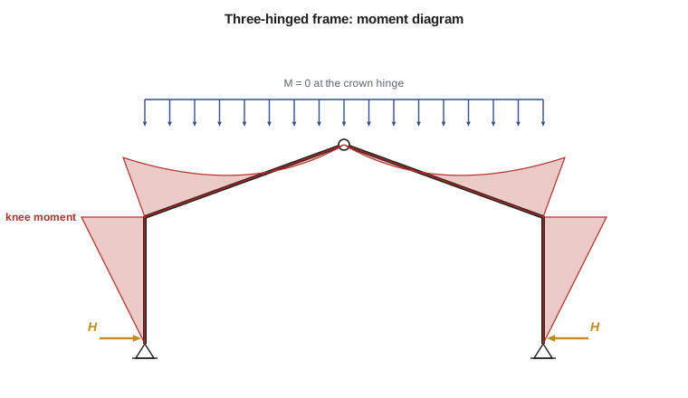
In lesson 3 we found the reactions of the salt shed's three-hinged frame. The inward thrust at the base produces large moments at the knees, and these govern the design. The hinge at the crown forces the moment to zero there, so the rafters are in mostly negative moment (tension on the outside), unlike a simple beam.
Worked problem
Knee and rafter moments in the three-hinged frame
Using the reactions from lesson 3 (\(A_y = E_y = 25\ \text{kips}\), \(A_x = E_x = 12.0\ \text{kips}\) inward; columns 16 ft, rafters rising 10 ft over 25 ft horizontally, load 1.0 kip/ft on plan), find the moment at the knee B and the moment along the rafter BC.
Show solution
- Column AB: the inward thrust of 12.0 kips acts at A, 16 ft below B. The moment at B is \(12.0 \times 16 = 192\ \text{kip·ft}\), with tension on the outside face.
- Rafter BC: at a horizontal distance x from B, the rafter is at height \(y = 16 + 0.4x\) above the base. Taking moments of the forces on the part of the frame from A to the section (hogging negative):
- \[M(x) = 25x - 12.0(16 + 0.4x) - 0.5x^2 = -192 + 20.2x - 0.5x^2\]
- At the crown, \(x = 25\): \(M = -192 + 505 - 312.5 \approx 0\), as the hinge requires. The small positive peak is at \(x = 20.2\ \text{ft}\), where \(M \approx +11.6\ \text{kip·ft}\).
Answer: The governing moment is 192 kip·ft at each knee, compared with \(wL^2/8 = 1.0(50^2)/8 = 312.5\ \text{kip·ft}\) for a simple beam of the same span. The thrust has redistributed the moment, which is why portal frames are economical. Frame members are often tapered, deepest at the knee and shallow at the crown and base, to follow this moment diagram.
Axial force and shear in inclined members
For an inclined member such as the rafter, resolve the forces at a section into components along and perpendicular to the member. If the rafter makes an angle θ with the horizontal, and the free body to one side of the section has a net vertical force V (up) and net horizontal force H (inward), then the axial force (compression positive here) is \(N = H\cos\theta + V\sin\theta\) and the shear perpendicular to the member is \(Q = V\cos\theta - H\sin\theta\). For the salt shed rafter just right of the knee (\(\theta = 21.8°\)), H is the 12.0-kip thrust and V is the 25-kip vertical reaction, giving an axial compression of about 20.4 kips and a shear of about 18.7 kips. The rafter is therefore a beam-column, designed for combined compression and bending.
Cantilever frames and brackets
Many frames are cantilevers fixed at one support: a sign structure, a canopy bracket, a crane runway bracket or a pipe support. Their analysis needs no reactions at all. Start at the free end and work toward the fixed support, cutting the frame at each section and summing the forces and moments on the free part. The crane bracket on a garage column, for example, carries the runway beam's reaction at an eccentricity from the column centerline, so it delivers to the column a vertical force and a moment equal to that force times the eccentricity. That moment then travels down the column to its base.
Worked problem
A crane runway bracket
A runway beam delivers a factored vertical load of 19 kips to a bracket welded to the face of a column, with the load acting 18 in. from the column centerline. The bracket is 20 ft above the fixed column base. Find the moment the bracket delivers to the column and the moment at the base from this load alone, assuming the column is a vertical cantilever.
Show solution
- The bracket transfers the load to the column as an axial force of 19 kips and a moment \(M = 19 \times 1.5 = 28.5\ \text{kip·ft}\).
- Below the bracket, the column carries the 19 kips compression and the constant moment of 28.5 kip·ft, so the base moment is also 28.5 kip·ft (there is no horizontal force in this load case).
Answer: Moment 28.5 kip·ft, constant from the bracket down to the base. In a real building the roof framing restrains the column top, which makes it indeterminate and reduces the base moment, but the cantilever model is a conservative first estimate.
Frame moments by computer
Sofia checks the three-hinged frame by computing the moment at many points around the frame from the reactions. The same short function works for any determinate plane frame once the reactions are known, because the moment at a section is just the sum of the moments of the forces on one side of it.
# Three-hinged frame: bases A(0,0), E(50,0); knees B(0,16), D(50,16); crown C(25,26); load 1.0 kip/ft on plan
w, span, h, rise = 1.0, 50.0, 16.0, 10.0
Ay = w * span / 2
Ax = (Ay * span / 2 - w * (span / 2) ** 2 / 2) / (h + rise)      # crown hinge condition, inward
print(f"Ay = {Ay:.1f} kips, thrust H = {Ax:.2f} kips")

def M_left(x, y):
    """Moment at section (x, y) on the left half; sagging (tension inside) positive."""
    return Ay * x - Ax * y - w * x ** 2 / 2

print("Column AB:")
for y in [0, 4, 8, 12, 16]:
    print(f"  y = {y:4.1f} ft   M = {M_left(0.0, y):7.1f} kip*ft")
print("Rafter BC:")
for i in range(6):
    x = i * 5.0; y = h + rise * x / (span / 2)
print(f" x = {x:4.1f} ft M = {M_left(x, y):7.1f} kip*ft")Ay = 25.0 kips, thrust H = 12.02 kips Column AB: y = 0.0 ft M = 0.0 kip*ft y = 4.0 ft M = -48.1 kip*ft y = 8.0 ft M = -96.2 kip*ft y = 12.0 ft M = -144.2 kip*ft y = 16.0 ft M = -192.3 kip*ft Rafter BC: x = 0.0 ft M = -192.3 kip*ft x = 5.0 ft M = -103.8 kip*ft x = 10.0 ft M = -40.4 kip*ft x = 15.0 ft M = -1.9 kip*ft x = 20.0 ft M = 11.5 kip*ft x = 25.0 ft M = 0.0 kip*ft
The table confirms the shape: the moment grows linearly up the column to its peak at the knee, then decreases along the rafter to zero at the crown hinge, with only a small reversal just before the crown.
Common mistakes
MistakeDrawing moment diagrams with an inconsistent sign convention around corners.
InsteadPlot moment on the tension side of each member; at a rigid corner the diagram stays on the same side (inside or outside) of the frame.
MistakeForgetting that a column's shear becomes the beam's axial force at a corner.
InsteadWrite horizontal and vertical joint equilibrium at each corner.
MistakeTreating rafter axial force as negligible.
InsteadRafters of portal frames carry substantial compression and must be designed as beam-columns.
MistakeAssuming a roller base can resist horizontal load.
InsteadA roller provides only a force perpendicular to its surface; all horizontal load goes to the other support.
Summary and key terms
- Frame members carry axial force, shear and moment; analyze each member as a beam with known end forces.
- At a rigid corner, moment is continuous and shear in one member becomes axial force in the other.
- Plot moment diagrams on the tension side of each member.
- Three-hinged frames develop base thrusts that produce large knee moments and reduce rafter moments.
- Inclined members need forces resolved along and perpendicular to their axes; rafters are beam-columns.
- Cantilever frames are analyzed from the free end, without finding reactions first.
- Frame
- A structure with rigid joints whose members carry bending, shear and axial force.
- Rigid joint
- A connection that maintains the angle between members and transmits moment.
- Portal frame
- A frame of two columns and a beam or rafters, often used for single-story buildings.
- Knee
- The corner joint where a column meets a beam or rafter in a portal frame.
- Beam-column
- A member carrying significant axial force and bending together.
- Tension side
- The face of a member in tension under bending; moment diagrams are drawn on it.
- Thrust
- The horizontal reaction at the base of an arch or three-hinged frame.
- Bracket
- A short cantilever attached to a column to support a beam or runway.
Practice problems
Work each problem on paper first, then reveal the answer to check.
At a 90° corner, a column carries a shear of 25 kN and no horizontal load acts at the joint. What axial force does the beam carry there?
Show answer
25 kN (tension or compression depending on direction).
A column 5 m high has a pin base and carries a horizontal reaction of 12 kN. Find the moment at its top.
Show answer
\(12 \times 5 = 60\ \text{kN·m}\).
Why are the rafters of a three-hinged frame in mostly negative moment?
Show answer
The base thrust acting at a lever arm below the rafter produces hogging moment that outweighs the sagging moment from the load.
A load of 50 kN acts on a bracket 0.3 m from a column centerline. What moment does it apply to the column?
Show answer
\(50 \times 0.3 = 15\ \text{kN·m}\).
What is the moment at a crown hinge?
Show answer
Zero.
Why does a portal frame on a pin and a roller send all horizontal load to one column?
Show answer
The roller cannot provide a horizontal reaction.
Lesson quiz · 5 questions
Score 60% or more to complete this lesson.
Create a free account to save your progress, take quizzes and earn a certificate.