
CIV-224 · Lesson 1 of 12 · 23 min
Structural systems, load paths and idealization
Mechanics of solids asked how a single member responds to the forces on it: how much it stretches, twists or bends, and how high its stresses climb. Structural analysis asks the question that comes first in practice. Given a whole structure, with its roof, floors, beams, columns, braces and foundations, and given the loads that nature and people will put on it, what forces end up in each member? Only once you know those internal forces can you size a beam, pick a column or check a connection. This course teaches the classical methods for answering that question for statically determinate structures, and introduces the ideas that extend them to indeterminate ones.
Throughout the course we follow one project. Kestrel Bay Engineering, a small consulting firm in Duluth, Minnesota, has been hired by the city to design a new municipal operations center: a single-story maintenance garage with steel roof trusses and a 5-ton bridge crane, a two-story office wing, a pedestrian bridge from the staff parking lot across a drainage channel, and a short-span road bridge on the access road. The team is led by Priya Raman, P.E., with Owen Lachance, an engineer intern (EI), doing most of the hand calculations, and Sofia Martel, a co-op student, checking them with short Python programs.
What structural analysis does
A structure is any assembly of members designed to carry loads safely to the ground. Analysis has three parts. First, you decide what loads act and where (lesson 2). Second, you replace the real structure by an idealized model: lines for members, symbols for supports, and simple rules for how joints behave. Third, you apply equilibrium, and when necessary compatibility of deformations, to find the reactions, internal forces and displacements. The model is always a simplification, and a large part of an engineer's judgment lies in choosing a model that is simple enough to solve but faithful enough to be safe.
Analysis is distinct from design. Analysis takes a structure as given and predicts how it behaves. Design chooses member sizes and details so that the predicted behavior meets the requirements of the building code and the client. In practice the two alternate: you assume sizes, analyze, check, resize and repeat. For statically determinate structures, the internal forces do not depend on member sizes, so one analysis is usually enough. For indeterminate structures, stiffer members attract more force, so the analysis has to be repeated as the sizes change, which is one reason software now does most of the arithmetic.
Common structural forms
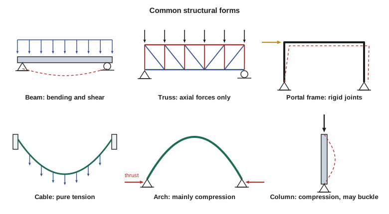
Most structures are built from a handful of member types, each suited to a particular way of carrying load.
- Tension members (ties, hangers, cables) carry axial tension. They are efficient because the whole cross-section works at the same stress and there is no buckling, but they need anchorage at both ends.
- Columns and struts carry axial compression. Long slender ones can buckle, so their capacity depends on length and end support as well as cross-section, as you saw with Euler's formula.
- Beams carry loads transverse to their length by bending and shear. They are the most common members in buildings and short bridges, but they are less efficient than axially loaded members because only the outer fibers reach high stress.
- Trusses are assemblies of straight members joined at their ends to form triangles. With loads applied at the joints, every member carries only axial force, so a truss can span much farther than a beam of the same weight.
- Frames are assemblies of beams and columns with rigid (moment-resisting) joints. Members carry axial force, shear and bending together. Portal frames are common for garages, warehouses and industrial buildings.
- Cables and arches carry load by changing shape. A cable takes the shape that puts it in pure tension under its load; an arch shaped to the same curve (inverted) is in pure compression. Lesson 7 covers both.
- Surface structures (slabs, walls, shells, folded plates) carry load in two directions. They are treated in later courses; in this course we model them as strips or as loads delivered to beams.
Load paths
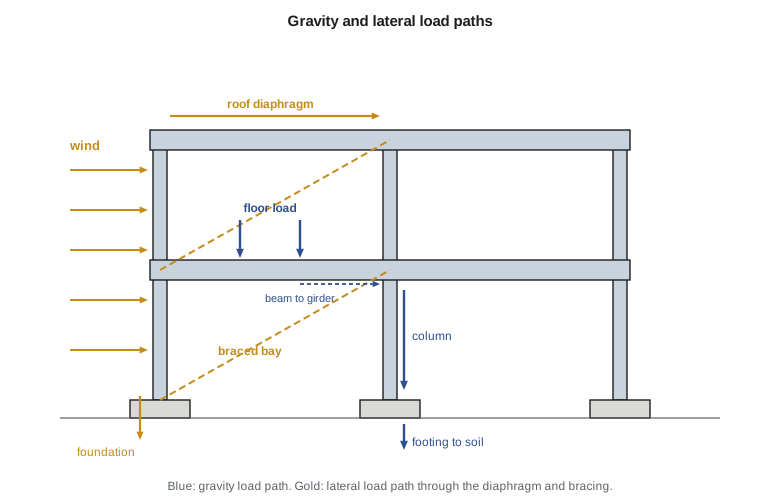
Every load must travel from where it is applied to the foundation through a continuous chain of members and connections. This chain is the load path, and tracing it is the first step in any analysis. In the operations center office wing, a filing cabinet on the second floor rests on the concrete topping of a composite steel deck. The deck spans between steel floor beams, which deliver their reactions to girders, which frame into columns, which carry the load down to footings, which spread it into the soil. Each element in the chain receives the reactions of the one above it as its loads.
Engineers trace two load paths in every building. The gravity load path carries dead load, occupancy live load and snow downward, as just described. The lateral load path carries wind and earthquake forces sideways: wind pressure on the wall cladding goes to girts, then to columns, then to the roof and floor diaphragms acting as deep horizontal beams, then to vertical bracing, shear walls or moment frames, and finally to the foundations. A building can be strong enough for gravity and still collapse sideways if any link in the lateral path is missing, which is why roof diaphragms and their connections get as much attention as beams.
Tributary areas
How much of a floor load does each beam carry? For one-way systems, where the deck spans in one direction between parallel beams, each beam carries the strip of floor that extends halfway to the adjacent beam on each side. This strip is the beam's tributary width, and its area over the beam's span is the tributary area. Multiplying the area load (kPa or psf) by the tributary width gives the line load on the beam (kN/m or kips/ft).
Worked problem
Line load on a floor beam
In the office wing, floor beams span 24 ft between girders and are spaced 8 ft apart. The floor dead load is 65 psf (slab, deck, ceiling and services) and the office live load is 50 psf. Find the line loads on a typical interior beam and on an edge beam.
Show solution
- An interior beam carries half the bay on each side, so its tributary width equals the spacing, 8 ft.
- \[w_D = 65 \times 8 = 520\ \text{lb/ft} \qquad w_L = 50 \times 8 = 400\ \text{lb/ft}\]
- An edge beam carries only half a bay, 4 ft, plus the weight of any cladding it supports: \(w_D = 260\ \text{lb/ft}\) plus cladding and \(w_L = 200\ \text{lb/ft}\).
Answer: The interior beam carries 0.52 kip/ft dead and 0.40 kip/ft live. Each girder then receives the beam reactions as point loads, \(0.52 \times 24/2 = 6.24\ \text{kips}\) dead from each side.
For two-way slabs supported on all four edges, the tributary area of each edge beam is found by drawing 45° lines from the corners of the panel. The long beams receive trapezoidal loads and the short beams triangular ones. Columns have tributary areas too: the rectangle bounded by lines halfway to the neighboring columns in each direction. Building codes allow live load reductions for members with large tributary areas, because it is unlikely that a large floor area is fully loaded at once; lesson 2 explains how.
Idealizing supports
Real supports are bolted base plates, bearing pads, embedded anchors and soil. In the model we replace them by ideal supports defined by which movements they prevent. Each prevented movement produces a reaction component.
| Support | Movements prevented | Reactions | Typical real example |
|---|---|---|---|
| Roller (or rocker, link) | Translation perpendicular to the surface | 1 force | Elastomeric bridge bearing, slotted connection |
| Pin (hinge) | Both translations | 2 forces | Bolted clip angle, simple base plate |
| Fixed | Both translations and rotation | 2 forces + 1 moment | Column cast into a footing, welded moment base |
| Guided (slider) | One translation and rotation | 1 force + 1 moment | Symmetry line in a model |
Choosing the support model has consequences. A column base plate with four anchor rods is neither a perfect pin nor perfectly fixed; it provides some rotational restraint. Modeling it as a pin is conservative for the column's moment at the top but unconservative for the drift of a portal frame. Experienced engineers bracket uncertain conditions by analyzing both extremes when the result matters.
Idealizing joints and members
Members are drawn as lines along their centroidal axes, and lengths are measured between the intersection points of those lines. Joints are idealized as either pinned, transmitting force but no moment, or rigid, keeping the angle between members fixed and transmitting moment. Most bolted steel connections that join only the web of a beam (shear tabs, clip angles) behave close to pins. Connections that join the flanges, by welding or end plates, are close to rigid. Truss joints are usually gusset plates that are fairly stiff, but because the members are slender and the loads are applied at the joints, the bending moments that develop are small, and the pin-jointed model gives accurate axial forces.
Loads are idealized too. A floor load is spread over an area, but on a beam it becomes a line load. A heavy piece of equipment sits on a few legs, but on a beam it becomes one or two point loads. A wind pressure varies over the height of a wall, but for a girt it becomes a uniform load. Each idealization should err on the side of producing the larger force in the members you are checking.
Units and significant figures
US practice uses customary units: lengths in feet and inches, forces in pounds and kips (1 kip = 1,000 lb), distributed loads in kips per foot, area loads in pounds per square foot, and moments in kip·ft or kip·in. Many manufacturers, international projects and some public agencies use SI, so keep the conversions handy: 1 kip = 4.448 kN, 1 ft = 0.3048 m, and 1 psf = 0.04788 kPa (47.88 Pa).
Loads are rarely known to better than a few percent, so three significant figures in a final answer is plenty. Carry more digits through intermediate steps, though, because subtracting nearly equal numbers (as happens with reactions on overhanging beams) can wipe out accuracy.
Checking: equilibrium as your safety net
For determinate structures, every answer can be checked by equilibrium. After finding reactions, sum forces and moments about a different point from the one you used. After finding member forces in a truss, check equilibrium at a joint you did not use. Students who build this habit catch most errors before they spread. Software does not remove the need: a common way models go wrong is a load entered in the wrong direction or units, and a quick check that the total vertical reaction equals the total applied load catches it immediately.
Sofia's first contribution to the project is a small checking routine. Given a list of applied loads and the computed reactions on a plane structure, it reports the residual force and moment, which should be zero to rounding.
# Equilibrium check for a plane structure: forces as (x, y, Fx, Fy), moments in kN*m (ccw +)
loads = [(2.0, 0.0, 0.0, -30.0), (4.5, 0.0, 0.0, -45.0), (7.5, 0.0, 0.0, -30.0)]  # girder point loads
reactions = [(0.0, 0.0, 0.0, 51.0), (7.5, 0.0, 0.0, 54.0)]                          # trial answers

def residual(forces, about=(0.0, 0.0)):
    sx = sum(f[2] for f in forces)
    sy = sum(f[3] for f in forces)
    m = sum((f[0] - about[0]) * f[3] - (f[1] - about[1]) * f[2] for f in forces)
    return sx, sy, m

for pt in [(0.0, 0.0), (7.5, 0.0), (3.0, 2.0)]:
    sx, sy, m = residual(loads + reactions, pt)
print(f"about {pt}: sum Fx = {sx:6.2f} sum Fy = {sy:6.2f} sum M = {m:7.2f}")about (0.0, 0.0): sum Fx = 0.00 sum Fy = 0.00 sum M = -82.50 about (7.5, 0.0): sum Fx = 0.00 sum Fy = 0.00 sum M = -82.50 about (3.0, 2.0): sum Fx = 0.00 sum Fy = 0.00 sum M = -82.50
Here the residual moment is not zero, so the trial reactions are wrong. Taking moments about the left support, the right reaction should be \((30 \times 2 + 45 \times 4.5 + 30 \times 7.5)/7.5 = 65\) and the left reaction \(105 - 65 = 40\), with the 30 kN load at the right support going straight into it. Changing the two reactions and running the program again gives zero residuals about every point, which is the sign of a correct answer.
Common mistakes
MistakeMeasuring member lengths to the face of a support or the edge of a flange.
InsteadMeasure along centroidal axes between joint intersection points, unless the model specifically represents a rigid end zone.
MistakeAssuming every connection is either perfectly pinned or perfectly fixed without thinking about it.
InsteadMatch the model to the detail, and when the result is sensitive, analyze both extremes.
MistakeForgetting the lateral load path because the gravity analysis worked.
InsteadTrace wind and earthquake forces from the cladding to the foundation through diaphragms and bracing.
MistakeUsing full bay width as the tributary width of an edge beam.
InsteadAn edge beam carries half a bay, plus any cladding or parapet it supports.
Summary and key terms
- Structural analysis finds reactions, internal forces and displacements in an idealized model of a structure.
- Members carry load axially (ties, struts, trusses, cables, arches) or by bending (beams, frames); axial action is more efficient.
- Every load needs a continuous gravity or lateral load path to the foundation.
- Tributary width or area converts area loads into line loads on beams and point loads on girders and columns.
- Rollers give one reaction, pins two, fixed supports three; joints are idealized as pinned or rigid.
- Check every determinate analysis with an independent equilibrium equation.
- Load path
- The chain of members and connections that carries a load to the foundation.
- Tributary area
- The area of floor or roof whose load is carried by a particular member.
- Idealization
- Replacing a real structure by a simplified model of lines, joints and ideal supports.
- Truss
- A triangulated assembly of members, loaded at its joints, whose members carry axial force.
- Frame
- An assembly of beams and columns with rigid joints that carries bending, shear and axial force.
- Diaphragm
- A floor or roof acting as a deep horizontal beam to carry lateral load to the vertical bracing.
- Pin support
- A support that prevents translation in both directions but allows rotation.
- Fixed support
- A support that prevents both translations and rotation.
Practice problems
Work each problem on paper first, then reveal the answer to check.
Beams spaced at 10 ft carry an 80 psf floor. What is the line load on an interior beam?
Show answer
\(80 \times 10 = 800\ \text{lb/ft} = 0.80\ \text{kip/ft}\).
How many reaction components does a fixed support provide in a plane structure?
Show answer
Three: two forces and one moment.
Why does a truss with loads only at its joints have members in pure axial force?
Show answer
With pinned joints and no loads between them, each member is a two-force member, so its force acts along its axis.
Name the elements of a lateral load path for wind on a single-story steel garage.
Show answer
Cladding, girts, columns, roof deck acting as a diaphragm, roof bracing or diaphragm chords, vertical bracing or moment frames, foundations.
An interior column sits on a grid of 8 m by 6 m bays. What is its tributary area?
Show answer
\(8 \times 6 = 48\ \text{m}^2\) (halfway to the neighbors in each direction).
Why does analysis of an indeterminate structure have to be repeated when members are resized?
Show answer
Internal forces depend on relative stiffness, so changing sizes changes the force distribution.
Lesson quiz · 5 questions
Score 60% or more to complete this lesson.
Create a free account to save your progress, take quizzes and earn a certificate.