
CIV-224 · Lesson 5 of 12 · 26 min
Shear and moment diagrams for determinate beams
You drew shear force and bending moment diagrams in mechanics of solids. In structural analysis they become everyday tools. They show where a beam needs the most strength, where its reinforcement must change faces, where splices and connections can go, and how it will deflect. This lesson reviews the method quickly and then extends it to the loadings that actually occur in buildings: point loads from framing beams, linearly varying loads from snow drifts and soil, overhangs, and beams with internal hinges. It also introduces moment diagrams drawn by parts, which you will need for deflections in lesson 10.
Sign convention and the basic relations
We keep the convention from CIV-221. Positive shear acts downward on the right face of a cut section's left part, and positive moment bends the beam concave upward (sagging, tension at the bottom). With a distributed load \(w(x)\) taken positive downward, equilibrium of a short element gives
A downward point load causes a downward jump in the shear diagram equal to the load, and a clockwise applied couple causes an upward jump in the moment diagram equal to the couple (reading left to right). These rules let you draw both diagrams from left to right using areas, with equilibrium equations written only to find the reactions.
The shapes follow from the order of each curve. With no load between points, shear is constant and moment linear. Under a uniform load, shear is linear and moment parabolic. Under a linearly varying load, shear is parabolic and moment cubic. The moment reaches a local maximum or minimum where the shear crosses zero, and its slope changes abruptly at point loads, where the shear jumps.
Girders with framing beam reactions
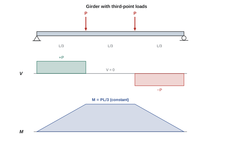
Most building girders are loaded by the reactions of the beams that frame into them, so their loading is a set of point loads. Between the loads the moment diagram is a series of straight lines, and the maximum moment is at one of the load points, the one where the shear changes sign.
Worked problem
An office wing girder
Floor beams spanning 24 ft at 8 ft spacing frame into both sides of a girder that also spans 24 ft, so the girder receives beam reactions at its third points. The beams carry factored loads of \(1.2(0.52) + 1.6(0.40) = 1.264\ \text{kip/ft}\). Find the girder's reactions, shear and maximum moment, ignoring its self-weight.
Show solution
- Each beam's end reaction is \(1.264 \times 24/2 = 15.17\ \text{kips}\), and beams frame in from both sides, so each third-point load is \(P = 30.3\ \text{kips}\).
- By symmetry each girder reaction is \(30.3\ \text{kips}\).
- Shear: \(+30.3\) from the left support to the first load, zero between the loads, \(-30.3\) from the second load to the right support.
- \[M_{\max} = 30.3 \times 8 = 243\ \text{kip·ft}\]
- The moment is constant between the two loads because the shear there is zero.
Answer: Reactions 30.3 kips, maximum moment 243 kip·ft over the middle third. A uniform load of the same total (60.7 kips over 24 ft) would give \(wL^2/8 = 182\ \text{kip·ft}\), so concentrating the load at the third points raises the moment by a third.
Linearly varying loads
Snow drifts against a higher roof, water and soil pressure on walls, and the load on a beam carrying part of a triangular tributary area all vary linearly. For a triangular load rising from zero at A to \(w_0\) at B over span L, the resultant is \(w_0 L/2\) acting at \(2L/3\) from A, so the reactions are \(w_0L/6\) at A and \(w_0L/3\) at B. At a distance x from A the load intensity is \(w_0x/L\), and the load to the left of the cut has resultant \(w_0x^2/(2L)\) acting at \(2x/3\) from A, a third of the way back from the cut. Hence
Setting \(V = 0\) gives \(x = L/\sqrt{3} = 0.577L\), and substituting gives \(M_{\max} = w_0L^2/(9\sqrt{3}) = 0.0642\,w_0L^2\). The maximum is shifted toward the heavy end, not at midspan.
Worked problem
A beam under a snow drift
Where the garage roof meets the taller office wing, snow drifts against the wall. A 20 ft roof beam running perpendicular to the wall carries a triangular drift load rising from zero at its far end A to 0.80 kip/ft at the wall end B (nominal load). Find the reactions and the maximum moment from the drift alone.
Show solution
- \[R_A = \frac{w_0L}{6} = \frac{0.80 \times 20}{6} = 2.67\ \text{kips} \qquad R_B = \frac{w_0L}{3} = 5.33\ \text{kips}\]
- Zero shear at \(x = 20/\sqrt{3} = 11.55\ \text{ft}\) from A.
- \[M_{\max} = 2.67(11.55) - \frac{0.80(11.55)^3}{6(20)} = 30.8 - 10.3 = 20.5\ \text{kip·ft}\]
- Check with the formula: \(0.0642 \times 0.80 \times 400 = 20.5\ \text{kip·ft}\).
Answer: The drift adds 20.5 kip·ft at 11.55 ft from the far end, plus a reaction of 5.33 kips at the wall. Combined with the uniform snow and dead load, the peak moment will lie between the drift peak and midspan; the program at the end of the lesson finds it.
Overhangs and points of inflection
An overhang creates negative moment over the support next to it, while the main span may still sag. Between the two regions the moment passes through zero at a point of inflection. Overhangs are used deliberately in canopies, cantilevered balconies and in continuous-looking beams, because the support moment reduces the sagging moment in the span.
Worked problem
A canopy beam over the garage doors
A canopy beam is supported by a pin at A and a roller at B, 20 ft apart, and overhangs 6 ft beyond B to C. It carries a factored uniform load of 0.70 kip/ft over its full 26 ft length. Find the reactions, the maximum positive and negative moments, and the point of inflection.
Show solution
- Total load 18.2 kips acting at 13 ft from A. Moments about A: \(20R_B = 18.2(13)\), so \(R_B = 11.83\ \text{kips}\) and \(R_A = 6.37\ \text{kips}\).
- Shear from A: \(V = 6.37 - 0.70x\), zero at \(x = 9.1\ \text{ft}\). Maximum positive moment \(M = 6.37^2/(2 \times 0.70) = 29.0\ \text{kip·ft}\).
- Moment at B from the overhang alone: \(M_B = -0.70(6^2)/2 = -12.6\ \text{kip·ft}\).
- Point of inflection: \(M(x) = 6.37x - 0.35x^2 = 0\) gives \(x = 18.2\ \text{ft}\) from A.
Answer: Maximum positive moment 29.0 kip·ft at 9.1 ft, maximum negative moment 12.6 kip·ft over B, inflection at 18.2 ft. A concrete canopy needs bottom bars in the span and top bars over B extending past the inflection point.
The deflected shape from the moment diagram
The moment diagram tells you the curvature of the beam, because curvature equals \(M/EI\). Where the moment is positive the beam is concave upward; where it is negative, concave downward; and at a point of inflection the curvature changes sign. Combined with the support conditions (zero deflection at supports, zero slope at fixed ends), this lets you sketch the deflected shape before computing anything. Sketching it is a good check on your diagrams and on later deflection calculations: the canopy beam sags between A and the inflection point, curves the other way near B, and its tip at C rises or drops depending on the relative stiffness and loads, which lesson 10 will tell us how to calculate.
Moment diagrams by parts
For deflection calculations it is often easier to draw the moment diagram as a sum of simple pieces than as one complicated curve. The idea is superposition: since the structure is linear, the moment from several loads equals the sum of the moments from each load alone. Drawing each piece as a cantilever from a chosen reference point, usually a support, gives shapes whose areas and centroids are standard: rectangles from couples, triangles from point loads, and parabolic spandrels from uniform loads.
| Shape | Area | Centroid from the zero end | Arises from |
|---|---|---|---|
| Rectangle, height h, base b | bh | b/2 | A couple |
| Triangle | bh/2 | 2b/3 from the vertex | A point load on a cantilever |
| Parabolic spandrel (2nd degree) | bh/3 | 3b/4 from the vertex | A uniform load on a cantilever |
| Cubic spandrel | bh/4 | 4b/5 from the vertex | A triangular load on a cantilever |
For a simply supported beam with a uniform load, for example, the moment by parts about the left support consists of a positive triangle from the right reaction, \(R_BL\) at the right end, and a negative parabolic spandrel from the load, \(-wL^2/2\). Their sum is the familiar parabola, but each piece has an area and centroid you can write down without integration. Lesson 10 uses exactly these pieces.
Inclined beams
Rafters, stair stringers and ramps are inclined. A gravity load on an inclined member can be specified per unit horizontal length (snow, which falls on the plan area) or per unit length along the slope (self-weight, which depends on the member's true length). Convert the latter to a load per horizontal length by multiplying by \(1/\cos\theta\). For a simply supported inclined beam with vertical reactions, the bending moment at any point is then the same as for a horizontal beam of the same horizontal span, while the shear and axial force are the vertical shear resolved perpendicular and parallel to the member. This result saves a lot of work on pitched roofs.
Diagrams by computer
Sofia's program handles any mix of point loads, uniform loads and linearly varying loads on a simply supported beam with optional overhangs. It finds the reactions, evaluates shear and moment along the beam, and reports the extreme values and points of inflection. Here it is applied to the drift beam with its uniform snow and dead load added.
# Simply supported beam A (x=0) to B (x=Lab) with optional overhang to Ltot; loads downward +
Lab, Ltot = 20.0, 20.0
points = []                                   # (x, P)
dist = [(0.0, 20.0, 1.2*0.40 + 1.6*0.84, 1.2*0.40 + 1.6*0.84),   # factored uniform dead + snow
        (0.0, 20.0, 0.0, 1.6*0.80)]                               # factored drift, 0 at A to peak at B

def pieces():
    for x, P in points: yield ("P", x, P)
    for a, b, w1, w2 in dist: yield ("D", a, b, w1, w2)

def left_effects(x):
    """Shear-like force and moment about x of loads left of x."""
    F = M = 0.0
    for p in pieces():
        if p[0] == "P" and p[1] < x:
            F += p[2]; M += p[2] * (x - p[1])
        elif p[0] == "D" and x > p[1]:
            a, b, w1, w2 = p[1:]; e = min(x, b); wl = w1 + (w2 - w1) * (e - a) / (b - a)
            R = (w1 + wl) / 2 * (e - a)                           # trapezoid resultant
            c = a + (e - a) * (w1 + 2 * wl) / (3 * (w1 + wl)) if w1 + wl else a
            F += R; M += R * (x - c)
    return F, M

tot = 0.0; mom = 0.0
for p in pieces():
    if p[0] == "P": tot += p[2]; mom += p[2] * p[1]
    else:
        a, b, w1, w2 = p[1:]; R = (w1 + w2) / 2 * (b - a)
        c = a + (b - a) * (w1 + 2 * w2) / (3 * (w1 + w2)); tot += R; mom += R * c
RB = mom / Lab; RA = tot - RB
def VM(x):
    F, M = left_effects(x)
    V = RA - F + (RB if x > Lab else 0.0)
    Mx = RA * x - M + (RB * (x - Lab) if x > Lab else 0.0)
    return V, Mx
xs = [i * Ltot / 6000 for i in range(6001)]
vals = [VM(x) for x in xs]
Mmax, xm = max((m, x) for (v, m), x in zip(vals, xs))
print(f"RA = {RA:.2f} kips, RB = {RB:.2f} kips")
print(f"Maximum moment {Mmax:.1f} kip*ft at x = {xm:.2f} ft (beam length {Lab} ft)")RA = 22.51 kips, RB = 26.77 kips Maximum moment 123.4 kip*ft at x = 10.43 ft (beam length 20.0 ft)
The peak moment falls a little past midspan, pulled toward the wall by the drift, as expected. Replacing the inputs with the canopy's overhang, or the girder's point loads, reproduces the hand results above.
Common mistakes
MistakePutting the maximum moment of a triangular load at midspan.
InsteadIt occurs where the shear is zero, at \(L/\sqrt{3}\) from the light end.
MistakeUsing the resultant of the whole distributed load to compute the moment at an interior section.
InsteadUse only the part of the load on one side of the section, with its own centroid.
MistakeIgnoring negative moment over the support of an overhanging beam.
InsteadCheck both the span moment and the support moment; both may need reinforcement or bracing.
MistakeForgetting that point loads make the moment diagram change slope, not jump.
InsteadPoint loads cause jumps in shear; only couples cause jumps in moment.
Summary and key terms
- \(dV/dx = -w\) and \(dM/dx = V\); jumps in shear at point loads and in moment at couples.
- Girders loaded by framing beams have straight-line moment diagrams with peaks at load points.
- A triangular load gives a cubic moment with \(M_{\max} = 0.0642\,w_0L^2\) at \(0.577L\) from the light end.
- Overhangs create negative support moments and points of inflection in the span.
- Moment diagrams by parts break a diagram into rectangles, triangles and spandrels with known areas and centroids.
- For inclined members with vertical loads per horizontal length, moments equal those of the horizontal projection.
- Point of inflection
- A point where the bending moment, and hence the curvature, changes sign.
- Moment diagram by parts
- A moment diagram drawn as the sum of simple shapes from individual loads.
- Spandrel
- The area between a parabolic or cubic curve and its tangent, used in moment diagrams by parts.
- Third-point loading
- Two equal point loads at one-third and two-thirds of the span.
- Drift load
- Additional snow load accumulated against a higher roof or obstruction.
- Superposition
- Adding the effects of individual loads on a linear structure to get the combined effect.
- Curvature
- The rate of change of slope of the deflected beam, equal to M/EI.
- Overhang
- The part of a beam extending beyond a support.
Practice problems
Work each problem on paper first, then reveal the answer to check.
A simply supported 30 ft beam carries 10 kips at each third point. Find \(M_{\max}\).
Show answer
\(10 \times 10 = 100\ \text{kip·ft}\).
Where is the maximum moment for a triangular load on a simple span?
Show answer
At \(L/\sqrt{3} = 0.577L\) from the zero-load end.
A 12 ft cantilever carries a triangular load from 0 at the tip to 0.6 kip/ft at the support. Find the support moment.
Show answer
Resultant \(3.6\ \text{kips}\) at 4 ft from the support: \(M = -14.4\ \text{kip·ft}\).
What does the sign of the moment tell you about a beam's deflected shape?
Show answer
Positive moment: concave upward; negative: concave downward.
What is the area of a second-degree parabolic spandrel of base b and height h?
Show answer
\(bh/3\), with its centroid at \(3b/4\) from the vertex.
A rafter is loaded by snow per horizontal length. How does its moment compare with that of a horizontal beam with the same horizontal span?
Show answer
It is the same, for vertical reactions.
Lesson quiz · 5 questions
Score 60% or more to complete this lesson.
Create a free account to save your progress, take quizzes and earn a certificate.