
CIV-224 · Lesson 8 of 12 · 24 min
Influence lines for beams and trusses
So far every load has had a fixed position. Bridges, crane runways, parking structures and the access road over the operations center's culvert carry loads that move. For a moving load the question changes. Instead of asking what the shear and moment are everywhere for a given load position, we ask: for a particular quantity at a particular point, such as the moment at midspan or the reaction at a support, where should the load be placed to make that quantity as large as possible, and how large does it get? The tool that answers this is the influence line.
What an influence line is
An influence line is a graph of the value of one response quantity (a reaction, a shear or moment at one section, or a member force) as a unit load moves across the structure. The horizontal axis is the position of the unit load; the vertical axis is the value of the quantity when the unit load is at that position. Do not confuse it with a shear or moment diagram. A moment diagram shows the moment at every section for one fixed loading; an influence line shows the moment at one fixed section for every position of the load.
Because the structure is linear, the effect of any real load follows from the influence line by scaling. A point load P at a position where the influence line ordinate is \(\eta\) produces a value \(P\eta\). A uniform load w over a stretch of the structure produces w times the area under the influence line over that stretch. And a group of loads produces the sum of their individual effects. Influence lines therefore turn the search for the worst loading into a geometry problem.
Influence lines by equilibrium
The direct way to construct an influence line is to place a unit load at a general position x, write equilibrium, and express the quantity as a function of x. For a simply supported beam AB of span L:
- Reaction at A: with the unit load at x from A, \(R_A = (L - x)/L\). The influence line is a straight line from 1 at A to 0 at B. Similarly \(R_B = x/L\), from 0 at A to 1 at B.
- Shear at a section C, a distance a from A (with \(b = L - a\)): when the load is to the right of C, the shear at C equals \(R_A = (L - x)/L\); when it is to the left, the shear equals \(R_A - 1 = -x/L\). The influence line is two parallel lines with a jump of 1 at C, from \(-a/L\) just left of C to \(+b/L\) just right of it.
- Moment at C: when the load is to the right of C, \(M_C = R_A\,a = a(L - x)/L\); to the left, \(M_C = R_B\,b = bx/L\). The influence line is a triangle with its peak at C, of height \(ab/L\).
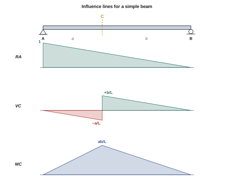
These shapes tell you at once where to put loads. For maximum moment at C, load the whole span, and put the heaviest point load at C. For maximum positive shear at C, load only the part to the right of C, because loads to the left produce negative shear there. For the maximum reaction at A, load the whole span with the heaviest point load at A.
Worked problem
Live load effects on the access road culvert slab
The access road crosses the channel on a simply supported slab-on-girder span of 60 ft. For one girder, find the maximum moment and the maximum positive shear at a section C 24 ft from A due to a uniform lane load of 0.64 kip/ft plus a single concentrated load of 25 kips, both as distributed to that girder.
Show solution
- Moment influence line at C: peak \(ab/L = 24 \times 36/60 = 14.4\ \text{ft}\). Area under the whole line \(= \tfrac{1}{2}(60)(14.4) = 432\ \text{ft}^2\).
- \[M_C = 0.64(432) + 25(14.4) = 276 + 360 = 636\ \text{kip·ft}\]
- Shear influence line at C: \(+36/60 = +0.6\) just right of C, falling to 0 at B; area of the positive part \(= \tfrac{1}{2}(36)(0.6) = 10.8\ \text{ft}\).
- \[V_C^+ = 0.64(10.8) + 25(0.6) = 6.9 + 15.0 = 21.9\ \text{kips}\]
Answer: Maximum moment at C is 636 kip·ft with the lane load over the whole span and the point load at C. Maximum positive shear is 21.9 kips with the lane load only on CB and the point load just right of C. Real design vehicles have several axles; lesson 9 handles them.
Overhangs and internal hinges
For a beam with an overhang, the influence lines simply extend beyond the support as straight lines. The influence line for the reaction at A on a beam ABC with the overhang BC continues past B below the axis, because a load on the overhang lifts A. The moment influence line at a section in the main span also extends past B with negative ordinates: a load on the overhang causes hogging moment at the section. For a section on the overhang itself, the moment influence line is zero for loads on the main span and grows linearly toward the tip, as for a cantilever. Internal hinges make influence lines kink at the hinge, and the segment beyond a hinge pivots about the next support. The quickest way to draw all of these is the Müller-Breslau principle.
The Müller-Breslau principle
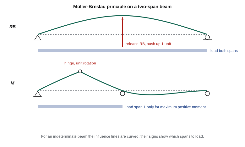
In 1886 Heinrich Müller-Breslau showed that the influence line for any force quantity has the same shape as the deflected shape of the structure when that quantity is released and given a unit displacement in its own direction. To draw the influence line for a reaction, remove the support and push that point up by one unit; the structure's new shape is the influence line. For shear at a section, cut the beam there so that it can slide but not rotate, and give it a unit relative sliding displacement with the two pieces staying parallel. For moment, insert a hinge at the section and give it a unit relative rotation.
For a determinate structure, releasing one restraint turns it into a mechanism, so the displaced shape is made of straight segments and is easy to draw. For an indeterminate structure, releasing one restraint leaves a structure that still has to bend, so the influence line is curved. The principle still gives its shape qualitatively, which is enough to decide which spans to load for the worst effect. This is the basis of pattern loading in continuous beams and frames: for maximum positive moment in a span, load that span and alternate spans; for maximum negative moment over a support, load the two adjacent spans and then every other span beyond.
Girders with floor systems
Many bridges and some building floors carry the deck on stringers that span between floor beams, and the floor beams deliver the load to the main girders or trusses only at panel points. A load between panel points reaches the girder as two point loads at the adjacent panel points, shared in proportion to its position, like the reactions of a simply supported stringer. The influence line for any quantity in the girder is therefore a straight line between panel points, even for sections between them. The influence line for shear in a panel, called the panel shear, is the same for every section within the panel, because no load is applied to the girder between its panel points.
Influence lines for trusses
Truss bridges carry their deck at the panel points of the top or bottom chord, so truss influence lines are also straight between panel points. To construct the influence line for a member force, place the unit load at each panel point in turn and find the member force by the method of sections, then join the values with straight lines.
For a parallel-chord truss, the method of sections links the member forces to beam quantities. A chord member's force equals the moment at the opposite panel point divided by the depth, so its influence line is the moment influence line for that panel point, scaled by \(1/d\). A diagonal's vertical component equals the panel shear, so its influence line is the panel shear influence line scaled by the ratio of the diagonal's length to the depth.
Worked problem
Influence line for a truss diagonal
A six-panel Pratt truss carries a bridge deck at its bottom chord panel points, with 10 ft panels and a depth of 7 ft. Find the influence line ordinates for the force in the diagonal of the second panel (between panel points 1 and 2), and its maximum tension and compression under a uniform live load of 1.0 kip/ft that can occupy any part of the span.
Show solution
- Panel shear in panel 2: unit load at panel point 1 gives \(V = R_A - 1 = 5/6 - 1 = -1/6\); at panel point 2 gives \(V = R_A = 4/6\). The line is straight between them and returns to zero at A and B.
- Diagonal length \(\sqrt{10^2 + 7^2} = 12.21\ \text{ft}\), so the force is panel shear × \(12.21/7 = 1.744\). Ordinates: \(-0.29\) at panel point 1 and \(+1.16\) at panel point 2.
- The line crosses zero between panel points 1 and 2 at \(x = 10 + 10(0.167/0.833) = 12.0\ \text{ft}\) from A.
- Maximum tension: load from 12 ft to B (48 ft long). Area of the positive triangle \(= \tfrac{1}{2}(48)(1.16) = 27.9\ \text{ft}\), so \(F = 1.0 \times 27.9 = 27.9\ \text{kips}\).
- Maximum compression: load from A to 12 ft. Area \(= \tfrac{1}{2}(12)(-0.29) = -1.74\ \text{ft}\), so \(F = -1.7\ \text{kips}\).
Answer: The diagonal sees 27.9 kips tension under the worst live load pattern, and a small compression of about 1.7 kips when only the left end is loaded. Under dead load alone it is in tension, so the net force may stay in tension, but the designer must check. Diagonals near midspan of long trusses can reverse, which is why some old bridges have crossed counter-diagonals in their central panels.
Influence lines by computer
Because an influence line is just the response to a unit load at many positions, a program can build it by brute force: move a unit load in small steps and record the quantity at each step. Sofia's version does this for the moment and shear at a section of a simple span, then integrates the ordinates to find the effect of a uniform load on the most unfavorable stretch, which reproduces the hand results.
L, a = 60.0, 24.0                        # span and section position (ft)
n = 2000
xs = [i * L / n for i in range(n + 1)]

def response(x, quantity):
    RA = (L - x) / L                     # unit load at x
    if quantity == "M":
        return RA * a - (a - x if x < a else 0.0)
    if quantity == "V":
        return RA - (1.0 if x < a else 0.0)

for q in ("M", "V"):
    eta = [response(x, q) for x in xs]
    dx = L / n
    pos = sum(max(e, 0.0) for e in eta) * dx
    neg = sum(min(e, 0.0) for e in eta) * dx
    peak = max(eta, key=abs)
    print(f"{q}: peak ordinate {peak:6.3f}, positive area {pos:7.2f}, negative area {neg:7.2f}")

w, P = 0.64, 25.0
Mmax = w * sum(max(response(x, "M"), 0) for x in xs) * L / n + P * max(response(x, "M") for x in xs)
Vmax = w * sum(max(response(x, "V"), 0) for x in xs) * L / n + P * max(response(x, "V") for x in xs)
print(f"Max moment at C = {Mmax:.0f} kip*ft, max positive shear at C = {Vmax:.1f} kips")M: peak ordinate 14.400, positive area 432.00, negative area 0.00 V: peak ordinate 0.600, positive area 10.81, negative area -4.79 Max moment at C = 636 kip*ft, max positive shear at C = 21.9 kips
The numerical areas agree with the triangle areas to within the step size. For an indeterminate structure, the same loop works if the response function calls a frame analysis program, which is how bridge design software builds influence surfaces for decks.
Common mistakes
MistakeConfusing an influence line with a moment diagram.
InsteadAn influence line shows one quantity at one point for all load positions; a moment diagram shows moments everywhere for one load case.
MistakeLoading the whole span for maximum shear at a section.
InsteadLoad only the part where the influence line is positive (or negative, for the opposite sign).
MistakeDrawing straight influence lines for indeterminate beams.
InsteadMüller-Breslau gives curved shapes for indeterminate structures; use them to choose spans to load.
MistakeForgetting that loads reach a truss only at panel points.
InsteadInfluence lines for trusses and floor-system girders are straight between panel points.
Summary and key terms
- An influence line gives the value of one quantity at one point as a unit load moves across the structure.
- Point load effect = P × ordinate; uniform load effect = w × area under the loaded part.
- For a simple beam: reactions are linear, shear at C jumps by 1 at C, moment at C is a triangle of height ab/L.
- Müller-Breslau: release the quantity and give it a unit displacement; the deflected shape is the influence line.
- Indeterminate influence lines are curved and lead to pattern loading.
- Truss member influence lines are scaled moment or panel shear influence lines, straight between panel points.
- Influence line
- A graph of a response quantity at one location as a unit load moves across the structure.
- Ordinate
- The value of an influence line at a given load position.
- Müller-Breslau principle
- The influence line for a force quantity has the shape of the structure's deflection when that quantity is released and given a unit displacement.
- Panel shear
- The shear in a panel of a truss or floor-system girder, constant within the panel.
- Pattern loading
- Loading selected spans of a continuous structure to produce the maximum effect at a point.
- Stringer
- A longitudinal deck member spanning between floor beams.
- Floor beam
- A transverse member carrying stringer reactions to the main girders or trusses.
- Counter-diagonal
- An extra diagonal in a truss panel to carry force of the opposite sign.
Practice problems
Work each problem on paper first, then reveal the answer to check.
For a 45 ft simple span, what is the peak moment influence line ordinate at a section 15 ft from A?
Show answer
\(15 \times 30/45 = 10\ \text{ft}\).
Where should a uniform live load be placed for maximum negative shear at a section of a simple beam?
Show answer
Only on the part of the span to the left of the section.
State the Müller-Breslau principle for a support reaction.
Show answer
Remove the support, push the point up a unit distance; the displaced shape is the reaction's influence line.
Why are influence lines for a truss straight between panel points?
Show answer
Loads reach the truss only through the floor system at the panel points, shared linearly by position.
For maximum positive moment in the middle span of a three-span continuous beam, which spans should be loaded?
Show answer
The middle span only (alternate spans), leaving the outer spans unloaded.
A section's moment influence line has an area of 400 ft². What moment does a uniform load of 0.8 kip/ft over the whole span produce?
Show answer
\(0.8 \times 400 = 320\ \text{kip·ft}\).
Lesson quiz · 5 questions
Score 60% or more to complete this lesson.
Create a free account to save your progress, take quizzes and earn a certificate.