
ARCH-210 · Lesson 9 of 12 · 21 min
Parametric and computational design
Joon-ho has been waiting all term for this lesson. He opens Grasshopper, places a slider, a point and a curve, connects them with wires, and in a minute has a row of timber louvers along the river wall of the boathouse that turn to open toward the view and close toward the path. When he drags the point, every louver turns at once. Professor Ferreira watches and then asks him to change the louver spacing to suit a standard board width, keep the angle within what the hardware allows, and produce a cutting list. It takes him the rest of the afternoon. 'That,' she says, 'is the difference between a parametric sketch and parametric design. The first makes a pattern. The second makes a building component that someone can order and install.'
What parametric design means
A parametric model is one in which geometry is defined by parameters and rules rather than drawn directly. Instead of drawing twenty louvers, you define one louver by its length, depth and angle, a rule for spacing them along a wall, and a rule for setting each angle, and the program generates the twenty louvers from those definitions. Change a parameter, and the whole set regenerates. You have already met this idea in BIM families in lesson 5 and in history-based modeling in lesson 2. Computational design extends it: the designer writes the rules, as a visual program or as code, to explore, analyze and optimize designs and to produce geometry and data that would be impossible or impractical to draw by hand.
Parametric thinking is older than the computer. Gaudí designed the Sagrada Família's columns and vaults with hanging chain models and rules of geometry; Frei Otto found the forms of tensile structures by experiment with soap films and nets; and builders have long used proportional systems to size every part of a building from one module. What the computer adds is speed, precision and the ability to handle thousands of variations and parts.
Visual programming
Most architects meet computational design through visual programming. Grasshopper, created by David Rutten and released for Rhino in 2007, and Dynamo, developed for Revit from about 2011, let you build programs by connecting components with wires on a canvas. Each component takes inputs, performs an operation and produces outputs: a slider produces a number; a division component splits a curve into points; a line component connects points; a rotation component turns geometry. The resulting graph is the design's recipe, visible and editable.
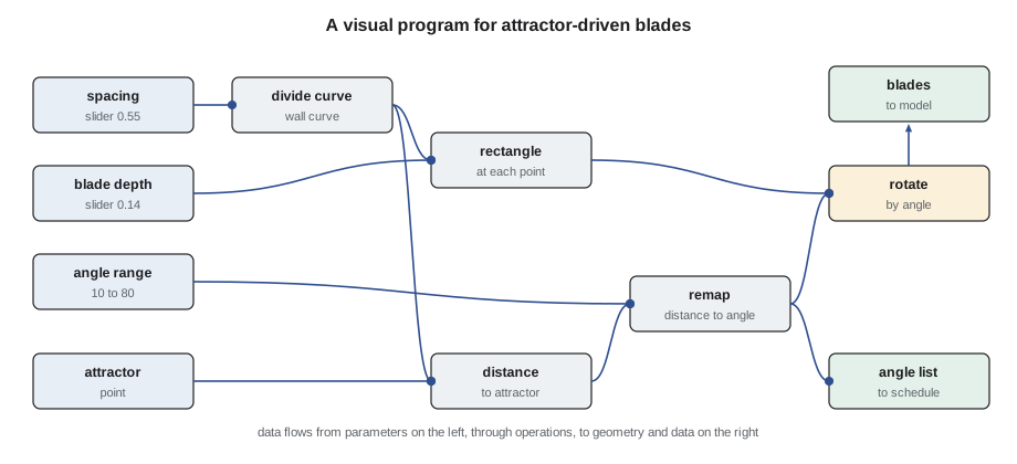
Two ideas make visual programs work. The first is that data flows: components run in order from inputs to outputs, and any change upstream recalculates everything downstream. The second is that most components work on lists. A division component outputs a list of twenty points, and a line component given two lists of twenty points makes twenty lines. When lists are nested, for example one list of points for each floor of a building, Grasshopper organizes them as data trees with branches. Learning to manage lists and trees, how to match, flatten, graft and shift them, is most of the difficulty of visual programming.
Scripting
Visual programs become hard to manage when they grow large. Many designers move on to scripting in a text language: Python, through GhPython and Rhino's script editor or through Dynamo's Python nodes; C# for Grasshopper components and Revit add-ins; and the application programming interfaces, or APIs, that let scripts create and modify Rhino geometry, Revit elements and Archicad objects. Text scripts handle loops, conditions and complex logic more clearly than graphs, are easier to version and reuse, and can automate tasks such as renaming hundreds of sheets, placing families from a spreadsheet or checking a model against rules.
The scripts in this course are written in plain Python so that they run anywhere, but the logic is the same as in a design tool. The first divides a façade into panels close to a target size, the kind of rule used to set out cladding.
# A parametric facade: divide a wall into panels and classify each by size (ft).
import math
def facade(width, height, target_w, target_h, min_frac=0.5):
    nx = max(1, round(width / target_w)); ny = max(1, round(height / target_h))
    pw, ph = width / nx, height / ny
    ok = min(pw / target_w, ph / target_h) >= min_frac
    return nx, ny, pw, ph, ok
for width in [24.0, 16.0, 32.5, 120.0]:
    nx, ny, pw, ph, ok = facade(width, 8.0, 4.0, 2.67)
print(f"wall {width:6.2f}: {nx} x {ny} panels of {pw:.3f} x {ph:.3f} {'ok' if ok else 'too small'}")wall 24.00: 6 x 3 panels of 4.000 x 2.667 ok wall 16.00: 4 x 3 panels of 4.000 x 2.667 ok wall 32.50: 8 x 3 panels of 4.062 x 2.667 ok wall 120.00: 30 x 3 panels of 4.000 x 2.667 ok
Attractors, patterns and data-driven form
One of the first techniques designers learn is the attractor: a point or curve whose distance from each element controls a property of that element, such as size, rotation, opening or transparency. Attractors produce smooth gradients across a façade or a ceiling and can be linked to real conditions, such as a view, an entrance, the sun's path or a structural load. The danger is decoration: a gradient that responds to nothing in particular is a pattern, not a design. The louvers on the boathouse respond to two real conditions: they open toward the river view and close toward the public path for privacy.
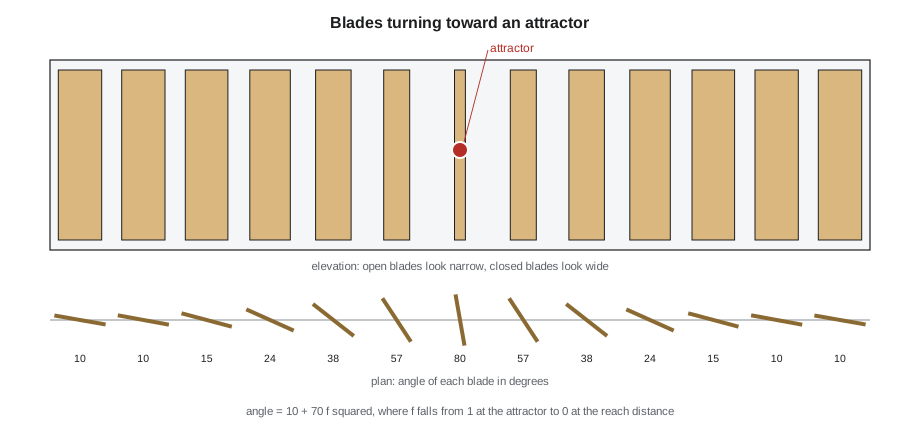
# Attractor-point louvers: each louver turns more the closer it is to the attractor.
import math
spacing, count = 1.83, 13                      # louver spacing (ft) and number of louvers
attractor = (11.0, 5.3)                         # point in elevation, e.g. a view or a doorway
max_turn, min_turn = 80, 10                      # degrees: open near the attractor, closed far away
reach = 10.0                                  # distance at which the effect fades out (ft)
row = []
for i in range(count):
    x = i * spacing
    d = math.hypot(x - attractor[0], 5.3 - attractor[1])
    f = max(0.0, 1 - d / reach)                  # 1 at the attractor, 0 beyond the reach
    angle = min_turn + (max_turn - min_turn) * f * f   # a smooth falloff
    row.append(round(angle))
print("louver angles (degrees):", row)
print("symbols:", "".join("|/-"[0 if a < 30 else 1 if a < 60 else 2] for a in row))louver angles (degrees): [10, 10, 15, 24, 38, 56, 80, 57, 38, 24, 15, 11, 10] symbols: ||||//-//||||
The angles fall off smoothly with distance and stay between the limits the hardware allows. In a real project the list of angles would go to a schedule and to the fabricator, along with a cutting list for the boards. The geometry and the data come from the same rules, so they cannot disagree.
Analysis, optimization and generative design
Computational design becomes most valuable when it is connected to analysis. Plug-ins such as Ladybug and Honeybee bring climate data, sun paths, radiation, daylight and energy simulation into Grasshopper, using validated engines such as Radiance and EnergyPlus. Karamba3D brings structural analysis; Kangaroo brings physics-based form-finding, so that a net or a shell can be relaxed into its natural shape under load, much as Frei Otto did with physical models. With analysis in the loop, a designer can see how a change in louver depth affects both summer sun on the glass and winter daylight in the room.
Optimization automates the search. An optimizer changes the parameters, runs the analysis, scores each result against goals and keeps searching for better results. Evolutionary solvers, such as Galapagos in Grasshopper, mimic natural selection, breeding good solutions and mutating them; multi-objective solvers, such as Octopus or Wallacei, search for the set of best compromises between conflicting goals, such as maximum daylight and minimum heat gain, called the Pareto front. Generative design tools in BIM programs apply the same idea to layouts and massing. Optimization is only as good as its goals: a design optimized for one measure can be poor in every other way, so architects use these tools to explore and inform decisions rather than to make them.
| Technique | What it does | Typical tools |
|---|---|---|
| Parametric modeling | Geometry from parameters and rules | Grasshopper, Dynamo, BIM families |
| Scripting and automation | Text programs that create geometry or automate tasks | Python, C#, Rhino and Revit APIs |
| Environmental analysis | Sun, daylight, energy and comfort in the design loop | Ladybug Tools, Radiance, EnergyPlus |
| Form-finding | Shapes found by simulating physical forces | Kangaroo, physical models |
| Optimization | Automated search for parameters that meet goals | Galapagos, Octopus, Wallacei, generative design tools |
Computational design in practice
Large firms have specialist computational design groups, such as the one at Zaha Hadid Architects and Foster and Partners' Specialist Modeling Group, which have worked on complex roofs, stadiums and towers since the late 1990s and 2000s. In many offices, though, the most common uses are modest and practical: setting out cladding panels, numbering and tagging thousands of elements, checking a model for errors, generating unit layouts for housing, testing massing options against zoning rules and daylight, and producing fabrication data. Computational skill is now one of the most valued skills among young architects, but the most effective computational designers are those who understand construction, because a rule that produces an unbuildable or unaffordable result is not a good rule.
Parametric models also have limits. A complex definition can be fragile, hard for anyone else to understand and slow to run. Document your graphs and scripts, name your parameters, group and label components, and keep the definition only as complicated as the design question needs. When the design is settled, the parametric output is usually baked into fixed geometry or BIM elements, so the documentation team works with ordinary model elements rather than a live script.
Worked problem
Louvers that someone can build
Joon-ho's first louver definition sets spacing freely and angles from 0 to 90 degrees. The fabricator says the boards come 5½ in wide, the pivot hardware allows angles from 10 to 80 degrees, and every louver must be the same length so that they can be cut in one batch. What should he change?
Show solution
- Set the spacing as a function of board width and a chosen overlap when closed, so that the louvers close fully at the minimum angle.
- Clamp the angles between 10 and 80 degrees in the remap step, as the script above does.
- Divide the wall into equal bays and make every louver the same length, adjusting the end bays rather than the louvers.
- Output a schedule of louver numbers and angles and a cutting list for the boards alongside the geometry.
Answer: Constraints from materials, hardware and fabrication belong inside the parametric definition, not as corrections afterward.
Exercise 9: a responsive screen
This exercise takes about six hours.
- Build a visual program or script that generates a screen of louvers or perforated panels for one wall of the boathouse.
- Drive at least one property with a real condition: a view point, the sun's position on December 21 and 21 June, or a privacy zone along the path.
- Include the fabrication constraints of a real board or panel size and hardware range.
- Output the geometry to the BIM model and a schedule of parts with their dimensions and angles.
- Deliverable: screenshots of the graph or the script, elevations of two versions, and the parts schedule.
Self-critique checklist
- Does my rule respond to a real condition rather than producing decoration?
- Are the material and hardware constraints built into the definition?
- Is my graph or script documented so that a classmate could use it?
- Do the geometry and the parts schedule come from the same rules?
From script to building element
In a BIM workflow, Dynamo and similar tools can place real building elements rather than abstract geometry: walls along curves, floors at every level of a massing, louver families at calculated points with their angle parameters set, or room tags renamed from a spreadsheet. Grasshopper can do the same through connections to Revit and Archicad, such as Rhino.Inside.Revit and the Grasshopper-Archicad live connection. This matters because the elements then carry categories, types and properties, so they appear in schedules, drawings and coordination like any other element, rather than as imported shapes that nobody can schedule or tag.
Common mistakes
MistakeMaking patterns that respond to nothing.
InsteadLink parameters to real conditions such as views, sun, privacy or structure.
MistakeIgnoring fabrication limits until the end.
InsteadPut material sizes, hardware ranges and tolerances into the definition from the start.
MistakeBuilding one huge, undocumented graph.
InsteadGroup, label and document components, and move complex logic into clean scripts.
MistakeLetting an optimizer make the decision.
InsteadUse optimization to explore trade-offs; judge the results against all the goals of the design.
MistakeKeeping the documentation model linked to a live script.
InsteadBake the final output into model elements once the design is settled.
Summary and key terms
- Parametric design defines geometry through parameters and rules, so that changes regenerate the whole design.
- Visual programming tools such as Grasshopper and Dynamo build programs from components and wires that process lists of data.
- Text scripting with Python or C# and software APIs handles complex logic and automation.
- Attractors and data-driven rules create gradients that should respond to real conditions.
- Analysis, form-finding and optimization bring performance into the design loop.
- Good computational design builds construction constraints into its rules and is documented for others.
- Parameter
- A named value, such as a spacing or an angle, that controls a design.
- Visual programming
- Programming by connecting components with wires on a canvas.
- Data tree
- A nested structure of lists used by Grasshopper to organize data.
- Attractor
- A point or curve whose distance from each element controls a property of that element.
- API
- Application programming interface: the functions a program exposes to scripts.
- Pareto front
- The set of solutions in which no goal can be improved without making another worse.
- Form-finding
- Finding a shape by simulating or modeling the forces acting on it.
Practice problems
Work each problem on paper first, then reveal the answer to check.
What happens downstream in a visual program when you change a slider?
Show answer
Every component that depends on it recalculates, and the geometry regenerates.
A wall is 32.5 ft wide and panels should be about 4 ft. How many panels and what width?
Show answer
32.5 ÷ 4 = 8.1, so 8 panels of about 4.06 ft.
Why is an attractor that responds to nothing a weak design move?
Show answer
It creates a pattern without a reason; good parametric rules link form to real conditions.
What does a multi-objective optimizer produce?
Show answer
A set of best compromises between conflicting goals, the Pareto front, rather than one answer.
Why bake parametric output into ordinary model elements?
Show answer
So the documentation team works with stable elements that are not affected by changes to a live script.
Lesson quiz · 5 questions
Score 60% or more to complete this lesson.
Create a free account to save your progress, take quizzes and earn a certificate.