
ARCH-210 · Lesson 12 of 12 · 22 min
Digital fabrication
For the final review, every student must bring a physical piece of the boathouse made directly from the digital model. Callum lasers a 1/4 in = 1 ft model of the warming hut from card, with slotted walls that click together; Wren mills a full-size section of the river wall's louver system from cedar on the school's CNC router; Ingrid prints the curved roof option in plastic; and Joon-ho, who has spent a week in the shop, brings a cutting list, a nesting layout and three finished louvers that pivot on real hardware. When the critic picks up Joon-ho's louver and turns it in his hand, the studio goes quiet. Professor Ferreira smiles. 'This is where digital design stops being a picture,' she says. 'A machine has read your file and made a thing. If the file was wrong, the thing is wrong.'
From file to factory
Digital fabrication means making physical objects directly from digital models, using computer-controlled machines. In architecture it ranges from cutting study models in the school shop to producing whole building components in factories: steel beams with every bolt hole drilled by machine, cross-laminated timber panels cut with all their openings and joints, curtain wall units, precast concrete with complex forms, and modular rooms assembled off site. The common idea is that the model, or data derived from it, goes straight to a machine, without anyone redrawing or measuring by hand. This is sometimes called file-to-factory.
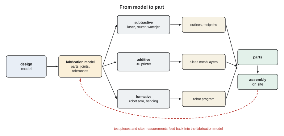
Fabrication processes are often grouped into three families. Subtractive processes remove material from a sheet or block, as laser cutting, waterjet cutting and CNC milling do. Additive processes build objects up layer by layer, as 3D printing does. Formative processes shape material by bending, folding, casting or forming, increasingly with robots. Each family has its own limits on size, material, precision and cost, and a good fabrication model is designed with those limits in mind.
Laser cutting
Laser cutters, the most common tools in architecture schools, cut or engrave flat sheets with a focused beam. A typical school machine has a bed of about 24 × 36 in and cuts card, paper, thin wood, acrylic and some fabrics. The machine reads vector outlines, usually from a DXF, PDF or SVG file, with layers or line settings telling it which lines to cut, which to score and which to engrave. The beam burns away a thin strip of material, the kerf, typically 0.004 to 0.012 in wide, so parts come out slightly smaller than drawn and slots slightly wider; precise joints must compensate. Some materials must never be laser cut: PVC and vinyl release chlorine gas that harms people and corrodes the machine, and some coated materials catch fire. Every school shop has a list of approved materials, and it should be followed exactly.
# Laser cutting a slot joint for a card model at 1:48: the slot must match the
# material thickness, corrected for the beam's kerf (sizes on the cutting bed in in).
t = 0.0625          # card thickness
kerf = 0.006      # width of material burned away by the beam
fit = 0.002       # extra clearance for a push fit
slot_drawn = t - kerf + fit
print(f"draw the slot {slot_drawn:.4f} in wide; it cuts to {slot_drawn + kerf:.4f} in for a {t} in card")
wall_full = 8     # real wall height in ft
model_h = wall_full * 12 / 48
print(f"a wall {wall_full} ft high is {model_h:.2f} in high in the model")draw the slot 0.0585 in wide; it cuts to 0.0645 in for a 0.0625 in card a wall 8 ft high is 2.00 in high in the model
Preparing a model for the laser cutter means unfolding it into flat parts, adding joints such as slots, tabs or finger joints sized for the material thickness, labeling each part with an engraved number, and nesting the parts on the sheet to save material. Thickness matters at small scales: a 1/4 in = 1 ft wall made from card 1/16 in thick represents a wall 3 in thick, too thin for the warming hut's real 10 in wall, so the model either uses thicker card, laminated layers, or accepts the abstraction.
CNC milling and routing
CNC, computer numerical control, routers and mills move a spinning cutter along programmed paths to cut sheets, carve surfaces and drill holes. A three-axis router moves the cutter left and right, forward and back, and up and down, which is enough for flat parts and shallow relief; five-axis machines also tilt the cutter, so they can machine undercuts and complex curved parts. The design model is converted into toolpaths in CAM, computer-aided manufacturing, software, which considers the cutter's diameter, speeds, depths of cut and the order of operations, and outputs machine instructions, usually as G-code.
The router's round cutter cannot cut a sharp inside corner, so joints designed with square inside corners will not fit. Fabrication designers add dog-bone or T-bone reliefs, small circular overcuts at inside corners, so that square parts slot together. Parts are held to the sheet with small tabs so that they do not move when cut free. Wood moves with humidity and has a grain direction, so joints are designed with small tolerances and parts are oriented with the grain where strength matters. Full-scale CNC routing of plywood is the basis of open-source building systems such as WikiHouse, in which a house's frame is cut from standard sheets and assembled by hand.
3D printing
3D printers build objects layer by layer from a mesh model, usually an STL or 3MF file, sliced into layers by slicing software. Fused deposition modeling, FDM, extrudes melted plastic filament and is cheap and common. Stereolithography, SLA, cures liquid resin with light and gives fine detail. Selective laser sintering, SLS, fuses powder with a laser and needs no support structures. Print models must be closed, manifold meshes with walls thick enough to print, oriented to reduce supports and printing time, and sized to the printer's build volume. The Euler check you saw in lesson 2 is exactly the kind of test slicing software performs.
At building scale, 3D printing of concrete and earth has moved from research into practice. Companies such as ICON in Texas have printed the walls of houses and small communities since the late 2010s, and several jurisdictions have begun to write rules for printed construction. Printed walls are produced quickly with little formwork, but they raise questions about reinforcement, insulation, openings, durability and code approval that are still being worked out.
Robots and large-scale fabrication
Industrial robot arms, borrowed from the car industry, can cut, mill, bend, glue, weld, lay bricks and assemble timber. Research groups such as Gramazio Kohler Research at ETH Zurich, which began robotic fabrication work in the mid-2000s, have built brick walls with every brick at a calculated angle, timber roofs assembled from thousands of unique pieces, and concrete forms printed and cast in place. In industry, timber fabricators use large CNC joinery machines to cut beams, columns and cross-laminated timber panels with every joint and opening, directly from the structural and architectural models; steel fabricators cut, drill and weld members from detailing models; and modular builders assemble whole rooms in factories. Prefabrication shortens construction time and improves quality, but it requires that the design be fixed and coordinated earlier, because a factory cannot easily change a panel once it is cut.
| Process | Family | Input | Typical use in architecture |
|---|---|---|---|
| Laser cutting | Subtractive | Vector outlines (DXF, PDF, SVG) | Study models, templates, thin panels |
| CNC routing and milling | Subtractive | Toolpaths from CAM (G-code) | Plywood parts, joinery, molds, façade panels |
| Waterjet and plasma cutting | Subtractive | Vector outlines | Metal and stone panels, steel plates |
| 3D printing | Additive | Sliced meshes (STL, 3MF) | Detailed models, prototypes, printed concrete walls |
| Robotic fabrication | Formative and assembly | Robot programs from the model | Brickwork, timber assembly, bending |
| Timber and steel CNC | Subtractive | Fabrication models and machine formats | Mass timber panels, beams, steel members |
Designing for fabrication
Designing for fabrication changes how you model. The design model describes the building; the fabrication model describes the parts: each one with its exact geometry, material, thickness, grain direction, joints, tolerances, label and assembly order. Tolerances are central. Every machine and material has a precision, every joint needs clearance, and every assembly on site must absorb the difference between the model and the real, slightly imperfect building it attaches to. Fabricators often say that the hardest part of digital fabrication is not the machine but the interface between the precise part and the imprecise site.
Fabrication also changes economics. Repetition is cheap in conventional construction; in digital fabrication, a machine can cut a hundred different parts as easily as a hundred identical ones, so variation can cost little more than repetition. Material, however, is still paid for, and waste matters for both cost and carbon. Nesting parts efficiently on sheets and stock lengths is part of good fabrication design. The script below plans cuts of the river-wall louvers and two shorter boards from standard stock lengths, allowing for the saw kerf, using a simple rule: place the longest pieces first, each in the first board with room.
# Cutting louver boards from stock lengths: first-fit decreasing, with the saw kerf (ft).
stock, kerf = 12, 0.0125
parts = [("L", 5.0, 13), ("S", 3.0, 4)]                       # (label, length, count)
pieces = sorted([(L, lab) for lab, L, n in parts for _ in range(n)], reverse=True)
boards = []                           # each board: [remaining length, list of pieces]
for L, lab in pieces:
    for b in boards:
        if b[0] >= L + kerf:
            b[0] -= L + kerf; b[1].append(lab); break
    else:
        boards.append([stock - L - kerf, [lab]])
used = sum(L for L, _ in pieces)
for k, (rem, labs) in enumerate(boards, 1):
    print(f"board {k}: {', '.join(labs)}  offcut {rem:.3f}")
print(f"{len(boards)} boards of {stock}, material yield {used / (len(boards) * stock):.0%}")board 1: L, L offcut 1.975 board 2: L, L offcut 1.975 board 3: L, L offcut 1.975 board 4: L, L offcut 1.975 board 5: L, L offcut 1.975 board 6: L, L offcut 1.975 board 7: L, S, S offcut 0.962 board 8: S, S offcut 5.975 8 boards of 12, material yield 80%
The yield, the fraction of purchased material that ends up in parts, tells you how much is wasted. A small change to the louver length, chosen so that two or three louvers fit exactly in a stock length with the kerf, can raise the yield considerably, which is the kind of decision that belongs in the parametric definition from lesson 9.
Safety and the shop
Fabrication machines are dangerous when used carelessly. Lasers start fires; routers throw parts and cut fingers; resin printers use chemicals that irritate skin; robots move with great force. Every shop has rules: training before use, approved materials only, eye and hearing protection, never leaving a laser unattended while it cuts, keeping hands clear of moving cutters, and reporting faults. Following them is part of professional practice, just as following building codes is.
Worked problem
Fabricating the louver system
Joon-ho must take his parametric louver design from lesson 9 to three working full-size louvers and a cutting list for all thirteen. What steps does he follow?
Show solution
- Fix the design inputs: board size 5½ × ¾ in cedar, louver length, pivot hardware and the angle range of 10 to 80 degrees.
- Build a fabrication model for one louver: the board with its pivot holes, chamfered edges and grain direction, and the steel brackets as purchased parts.
- Generate CNC toolpaths for the pivot holes and chamfers, with tabs, and a cutting list for the boards nested on stock lengths.
- Mill one test piece, check the fit of the hardware, adjust the hole size for the real fit, then mill the three louvers and assemble them on a mock-up frame.
- Record the final dimensions and settings back in the model, so that the full set can be made from the corrected data.
Answer: A fabrication workflow includes design inputs from real materials and hardware, a test piece, and a loop back to the model.
Exercise 12: from model to object
This exercise takes about eight hours, including shop time.
- Choose one element of the boathouse: the whole building as a scale model, a wall assembly section, the louver system or a roof option.
- Prepare a fabrication model with parts, joints, tolerances and labels suited to one fabrication process.
- Produce the machine data: nested cutting files, CNC toolpaths or a sliced print, and a cutting list or parts schedule.
- Fabricate a test piece, adjust the model from what you learn, and then make the final object.
- Deliverable: the object, the fabrication drawings or files, and a one-page record of what changed between the test piece and the final piece.
Self-critique checklist
- Did I design joints for the real material thickness, kerf or cutter diameter?
- Did I make and learn from a test piece before the final run?
- Are my parts labeled and nested to reduce waste?
- Did I follow the shop's rules for materials and safety?
Common mistakes
MistakeSending a design model straight to a machine.
InsteadPrepare a fabrication model with parts, joints, tolerances and labels for the process.
MistakeIgnoring kerf and cutter diameter.
InsteadOffset cut lines for kerf, and add dog-bone reliefs at inside corners for routed joints.
MistakeSkipping the test piece.
InsteadMake a test piece to check fit and settings, then update the model.
MistakeLaser cutting unapproved materials such as PVC.
InsteadUse only materials on the shop's approved list.
MistakeTreating variation as free and material as unlimited.
InsteadNest parts and choose dimensions that suit stock sizes to reduce waste.
Summary and key terms
- Digital fabrication makes physical parts directly from digital models, from study models to building components.
- Subtractive, additive and formative processes each have limits of size, material, precision and cost.
- Laser cutters read vector outlines and remove a kerf; CNC routers follow toolpaths and cannot cut sharp inside corners.
- 3D printers need closed, manifold meshes; large-scale printing and robotics are entering practice.
- Fabrication models describe parts, joints, tolerances, labels and assembly order.
- Nesting and stock-aware design reduce waste; safety rules are part of professional practice.
- Digital fabrication
- Making physical objects directly from digital models with computer-controlled machines.
- Kerf
- The width of material removed by a cutting beam, blade or tool.
- CNC
- Computer numerical control: machines that follow programmed toolpaths.
- CAM
- Computer-aided manufacturing: software that turns geometry into toolpaths and machine code.
- G-code
- A common language of machine instructions for CNC machines.
- Dog-bone relief
- A small overcut at an inside corner so that square parts fit a routed slot.
- Nesting
- Arranging parts on sheets or stock lengths to reduce waste.
Practice problems
Work each problem on paper first, then reveal the answer to check.
Why do laser-cut slots come out wider than drawn?
Show answer
The beam burns away a kerf of material, so cuts are wider by about the kerf width.
Why can a CNC router not cut a sharp inside corner?
Show answer
Its cutter is round, so it leaves a radius equal to the cutter's radius; dog-bone reliefs are added to allow square parts to fit.
What must be true of a mesh before it is 3D printed?
Show answer
It must be closed and manifold, with walls thick enough to print and a size within the build volume.
How many 5 ft louvers fit in a 12 ft board with a 1/8 in kerf?
Show answer
Two: 2 × (5 + 0.0125) = 10.025 ft, and a third would need 15.04 ft.
Why must a design be fixed earlier when it is prefabricated?
Show answer
A factory cuts parts precisely from the model, and changing them after cutting is costly or impossible.
Lesson quiz · 5 questions
Score 60% or more to complete this lesson.
Create a free account to save your progress, take quizzes and earn a certificate.