
ARCH-210 · Lesson 8 of 12 · 21 min
Rendering and visualization
The night before the midterm review, the studio's render queue is full. Callum has been rendering the boathouse at dusk for six hours and the image is still grainy; Wren, using a real-time renderer linked to her model, has made forty views in an evening but they all look a little like a video game. Ingrid has typed a description of the boathouse into an image generator and has a gorgeous picture with a timber roof structure that could not possibly stand up. At the review, the critic, a practicing architect, looks at all three and asks the same question each time: 'What is this image for?'
What visualization is for
Architects make images for different purposes, and the purpose should decide the method. Design images help the designer and the team test a decision: how light enters a room, how a material looks next to another, how a façade reads from the street. They should be quick and honest. Presentation images persuade a client, a jury, a community or an approval authority; they need atmosphere and polish, but they also carry an ethical responsibility not to mislead. Technical images, such as daylight studies or glare analyses, must be physically accurate. Diagrams explain ideas and often leave realism out entirely. A rendering is never just a picture of a building; it is an argument about it.
Cameras and composition
Every rendering starts with a camera: a position, a target and a lens. Architectural cameras usually stand at eye height, about 5 ft 3 in, unless there is a reason to show a bird's-eye or a worm's-eye view. The focal length controls the field of view: a lens equivalent to 35 millimeters on a full-frame camera is close to natural human vision; very wide lenses, such as 16 or 18 millimeters, exaggerate depth and make rooms look larger than they are, which is a common way to mislead. Vertical lines should usually stay vertical, achieved with two-point perspective correction or a shift lens, as architectural photographers do. Composition follows the same principles as photography and drawing: a clear subject, a foreground, middle ground and background, and edges that do not cut awkwardly through important elements.
Materials
Modern renderers use physically based materials, defined by a few properties that describe how a surface interacts with light. The albedo, or base reflectance, describes the tint and lightness of the surface under neutral light. Roughness describes how blurry its reflections are, from a mirror to a matte plaster. Metalness distinguishes metals, which reflect light tinted by their own hue, from dielectrics such as wood, stone and plastic. Normal and bump maps add small surface detail without extra geometry, and displacement maps actually move the geometry. Transparency, refraction and translucency describe glass, water and thin fabrics. Textures, images mapped onto surfaces, give wood grain, brick courses and concrete formwork marks; they must be mapped at the right scale, or a brick will look as large as a door.
A BIM model's materials carry both rendering appearance and construction data. In a well-set-up template, the material Cedar Siding has a texture and roughness for rendering, a hatch pattern for drawings, and data for takeoffs and specifications. Keeping these together means that the renderings, the drawings and the quantities describe the same building.
Light
Light makes a rendering. Exterior scenes use a sun, set from the project's location, date and time, and a sky, either a physical sky model or a high dynamic range image, HDRI, photographed of a real sky that lights the scene from every direction. Interiors add artificial lights, ideally using the photometric data files, IES files, published by manufacturers for each fitting, so that the light has the right brightness and distribution. Exposure, white balance and tone mapping then convert the physically calculated light into an image a screen can show, much as a camera does.
For the boathouse at Kestrel Point, setting the real location matters: at about 45 degrees north the winter sun at noon is low, so the warming hut's south windows receive long, raking light in January, and the image should show that rather than a generic summer afternoon.
How renderers work
There are two broad families of rendering methods. Rasterization, used by game engines and most real-time renderers, projects each triangle of the mesh onto the screen and fills in the pixels it covers, using fast approximations for shadows, reflections and indirect light. It can draw millions of triangles many times a second. Ray tracing works the other way: for each pixel, it sends a ray from the camera into the scene, finds the first surface it hits, and then sends more rays from that point toward lights to find shadows and in other directions to find reflections and indirect light. Path tracing, the method behind most photorealistic renderers, follows many random light paths per pixel and averages them, which is why a path-traced image starts grainy and becomes clean as more samples accumulate.
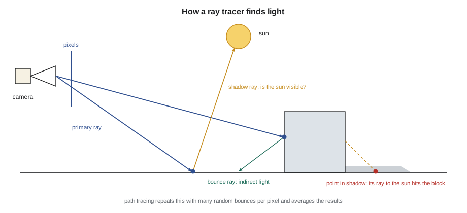
The central step in ray tracing is finding where a ray meets a surface. For a ray starting at point o in direction d, and a plane through point p₀ with normal n, the distance along the ray to the hit point is:
The brightness of a matte surface lit by the sun follows Lambert's cosine law, where ρ is the surface's albedo and l is the direction toward the sun:
The script below is a complete, if tiny, ray tracer. It sends a ray through each character of a small text image, in which the block appears as # signs and brighter ground as later symbols in the sequence .:-=+*@, tests whether the ray hits a block standing on the ground, and if not, where it hits the ground. For each ground point it computes the Lambert brightness and then traces a second ray toward the sun: if that ray hits the block, the point is in shadow.
# A tiny ray tracer: rays from a camera hit the ground plane, which is lit by the sun.
# A box standing on the ground casts a shadow, found by tracing a ray toward the sun.
import math
def sub(a, b): return (a[0] - b[0], a[1] - b[1], a[2] - b[2])
def dot(a, b): return a[0] * b[0] + a[1] * b[1] + a[2] * b[2]
def norm(a):
    l = math.sqrt(dot(a, a)); return (a[0] / l, a[1] / l, a[2] / l)
def hit_plane(o, d, p0, n):
    den = dot(d, n)
    if abs(den) < 1e-9: return None
    t = dot(sub(p0, o), n) / den
    return t if t > 0 else None
def hit_box(o, d, lo, hi):                      # slab method for an axis-aligned box
    t0, t1 = -1e9, 1e9
    for i in range(3):
        if abs(d[i]) < 1e-12:
            if not lo[i] <= o[i] <= hi[i]: return False
            continue
        a, b = (lo[i] - o[i]) / d[i], (hi[i] - o[i]) / d[i]
        t0, t1 = max(t0, min(a, b)), min(t1, max(a, b))
    return t1 >= max(t0, 1e-6)
sun = norm((0.7, 0.4, 0.6))                  # direction toward the sun
ground_n, albedo = (0, 0, 1), 0.6
box_lo, box_hi = (4, 4, 0), (6, 6, 3)           # a block 2 x 2 x 3 units
cam = (5, -7, 6)
rows = []
for j in range(12):
    line = ""
    for i in range(36):
        d = norm((-1.3 + i * 0.36 - cam[0], 7 - cam[1], 3.0 - j * 0.45 - cam[2]))
        if hit_box(cam, d, box_lo, box_hi):
            line += "#"; continue
        t = hit_plane(cam, d, (0, 0, 0), ground_n)
        if t is None:
            line += " "; continue
        p = (cam[0] + t * d[0], cam[1] + t * d[1], 0.0)
        shade = albedo * max(0.0, dot(ground_n, sun))
        if hit_box((p[0], p[1], 1e-4), sun, box_lo, box_hi):
            shade *= 0.25                        # in shadow: sky light only
        line += ".:-=+*@"[min(6, int(shade * 12))]
    rows.append(line)
print("\n".join(rows))
print(f"sun altitude {math.degrees(math.asin(sun[2])):.1f} degrees, lit ground brightness {albedo * sun[2]:.2f}")++++++++++++++++++++++++++++++++++++ +++++++++++++++######+++++++++++++++ ++++++++++++++########++++++++++++++ ++++++++++++++########++++++++++++++ ++++++++++++++########++++++++++++++ ++++++++++++++########++++++++++++++ ++++++++++++++########++++++++++++++ ++++++++++++++########++++++++++++++ +++++++++++++:########++++++++++++++ +++++++++:::::########++++++++++++++ ++++::::::::::########++++++++++++++ +::::::::::::::::::+++++++++++++++++ sun altitude 36.7 degrees, lit ground brightness 0.36
Real renderers do exactly this, with millions of rays, many bounces, complex materials and clever acceleration structures that avoid testing every ray against every triangle. In 1986 James Kajiya described the rendering equation, which expresses all of this in a single integral for the light leaving each point; path tracing is a way of estimating that integral by sampling. Graphics cards have included dedicated ray-tracing hardware since about 2018, which is why real-time renderers have become so much more realistic in recent years.
Real-time and offline rendering
Real-time renderers, such as Enscape, Twinmotion, Lumion, D5 Render and Unreal Engine, display the scene interactively, often linked live to the BIM or Rhino model so that design changes appear immediately. They are excellent for design reviews, walkthroughs, virtual reality and quick images, and they increasingly use hybrid ray tracing for quality. Offline renderers, such as V-Ray, Corona and Blender's Cycles, take seconds to hours per image but give the most control over light and materials. Many offices use real-time tools throughout design and offline tools for a few final images.
| Approach | Speed | Strengths | Typical use |
|---|---|---|---|
| Rasterization, real-time | Many frames per second | Interactive, live link, virtual reality | Design reviews, walkthroughs, quick images |
| Hybrid real-time ray tracing | Interactive to seconds | Better reflections and shadows, still interactive | Client presentations, animations |
| Path tracing, offline | Seconds to hours per image | Physically accurate light and materials | Final images, competitions |
| Non-photorealistic rendering | Fast | Clarity, abstraction, focus on ideas | Diagrams, early design, explanation |
Post-production, people and context
Most finished images are adjusted after rendering: exposure and white balance are corrected, entourage such as people, trees and vehicles is added, and atmosphere such as haze or rain is painted in. Entourage gives scale and tells a story about how the building is used, but it also shapes how people read the project; a rendering full of smiling, identical people in summer clothing tells a different story from one showing the building in January slush. Context, the neighboring buildings, the street and the landscape, should be included honestly, at their real height and in their real condition.
Virtual reality, animation and other media
Real-time engines make it easy to walk through a design in virtual reality, which helps clients and users understand scale and sequence in a way that images do not. Augmented reality overlays a model on the real site through a tablet or headset, useful for showing a proposal in place and, on construction sites, for checking installed work against the model. Animations and fly-throughs show movement and sequence. Panoramic images can be viewed on a phone. Each medium suits different audiences and questions.
AI image generation and honesty
Since 2022, image generators based on diffusion models have made it possible to create persuasive architectural images from text prompts, sketches or simple massing models in seconds. Tools built into design software, such as AI visualizers in BIM programs, and general tools used by designers can be helpful in the earliest stage, when the aim is to explore moods, materials and atmospheres quickly. They also raise two serious problems. They invent: the image may contain structure, details or materials that do not exist in the design and could not be built. And they mislead: a client or a community shown such an image may believe it represents a real proposal. Many offices now label AI-generated images clearly and use them only internally or for mood studies. An architect's image is a promise about a building; it should be one the architect can keep.
Worked problem
Choosing a method for three images
For the final review of the warming hut, the team needs a daylight study of the warming room on December 21 at noon, an evening exterior view showing the hut glowing on the frozen river, and a series of interior views to test bench and window layouts during design. Which methods should they use?
Show solution
- Daylight study: a physically based renderer or a dedicated daylight tool with the real location, date and sky, and calibrated materials, because the result must be accurate.
- Evening exterior: an offline path-traced render with IES data for the interior lights and a dusk sky, then careful post-production; atmosphere matters, but the light levels should still be plausible.
- Design interior views: a real-time renderer linked to the model, so that each layout change can be reviewed in seconds.
- Label any AI-assisted mood images as such, and keep them out of the formal review.
Answer: Match the method to the purpose: accuracy for analysis, atmosphere with honesty for presentation, speed for design.
Exercise 8: one view, three ways
This exercise takes about five hours.
- Choose one interior and one exterior view of the boathouse model and set physically based materials for siding, roofing, glass, wood floor and concrete.
- Render each view in a real-time renderer and in an offline path tracer, using the real location and two times of day.
- Make a third, non-photorealistic version of the exterior view that explains one design idea as a diagram.
- Compare the three versions for time taken, accuracy and what each one communicates.
- Deliverable: a sheet with all six images, the settings used and a paragraph on which you would show to a client and why.
Self-critique checklist
- Are my camera heights and lenses honest about the size of the spaces?
- Are textures mapped at the correct scale?
- Is the sun set from the real location and date?
- Does each image have a clear purpose, and is any AI-assisted image labeled?
Common mistakes
MistakeUsing very wide lenses to make spaces look bigger.
InsteadUse focal lengths close to human vision unless there is a clear reason not to.
MistakeRendering with default materials and generic sun.
InsteadUse physically based materials and the project's real location, date and time.
MistakeLeaving textures at the wrong scale.
InsteadCheck texture sizes against real dimensions, such as brick courses or board widths.
MistakePresenting AI-generated images as the design.
InsteadLabel them and use them for mood studies; show images that represent the real proposal.
MistakeChoosing a renderer before deciding what the image is for.
InsteadDecide the purpose first: analysis, design review, presentation or diagram.
Summary and key terms
- Visualization serves design, presentation, analysis and explanation, and the purpose should choose the method.
- Cameras, lenses and composition shape how a space is perceived.
- Physically based materials use albedo, roughness, metalness and maps to describe surfaces.
- Sun, sky, HDRI and IES lights provide realistic illumination when set from real data.
- Rasterization is fast and interactive; ray and path tracing follow light physically and are more accurate.
- Images carry ethical weight: they should represent the real design honestly, including any AI-generated content.
- Rendering
- The process of calculating an image from a 3D model, its materials, lights and camera.
- Rasterization
- Rendering by projecting triangles onto the screen and filling in the pixels they cover.
- Ray tracing
- Rendering by following rays from the camera into the scene and toward lights.
- Path tracing
- Ray tracing that averages many random light paths per pixel to estimate global illumination.
- HDRI
- A high dynamic range image of a real environment used to light a scene.
- IES file
- A photometric data file describing the light distribution of a fitting.
- Albedo
- The base tint and reflectance of a surface under neutral light.
Practice problems
Work each problem on paper first, then reveal the answer to check.
Why does a path-traced image look grainy at first?
Show answer
It averages random light paths per pixel; with few samples the average is noisy, and it smooths as samples accumulate.
What is an HDRI used for?
Show answer
To light a scene with the brightness and tint of a real sky or environment from every direction.
A ray starts at o = (0, 0, 4) and travels in direction d = (0, 0.6, −0.8). Where does it hit the ground plane z = 0?
Show answer
t = (0 − 4) ÷ (−0.8) = 5, so the hit point is (0, 3, 0).
Name one strength of real-time rendering and one of offline rendering.
Show answer
Real-time: interactive and linked live to the model. Offline: physically accurate light and materials.
Give two risks of using AI image generators for presentations.
Show answer
They can invent unbuildable or undesigned details, and they can mislead viewers into thinking the image is the real proposal.
Lesson quiz · 5 questions
Score 60% or more to complete this lesson.
Create a free account to save your progress, take quizzes and earn a certificate.