
ARCH-210 · Lesson 1 of 12 · 24 min
Digital tools in practice
The digital studio at Elmhurst School of Architecture is a long room on the third floor with forty workstations, a plotter that hums all through review week, and a back corner where a laser cutter and two 3D printers sit behind glass. On the first afternoon of term, Professor Lucía Ferreira, who spent twelve years as the BIM manager of a mid-sized firm in Minneapolis before she started teaching, asks the class to open nothing at all. 'Leave the computers off for an hour,' she says. 'Last year you learned to draw by hand and in 2D CAD. This term you will learn to build buildings inside the computer, as models that know what they are made of. Before you touch the software, I want you to understand what these tools are for, what they are bad at, and how an office actually uses them.' Wren, who spent the summer working in a small practice, says the first thing she learned there was that nobody cared which button she pressed, only whether the drawings were right and the file was where it was supposed to be.
Why architects use digital tools
Architects use computers for the same reasons they once used drafting boards, parallel rules and ink: to think about a building, to test it, to describe it so that others can build it, and to communicate it to clients, consultants, authorities and the public. Digital tools did not change those purposes. What they changed is how fast a design can be revised, how much information can be attached to it, how many people can work on it at once, and how directly a design can be connected to analysis, cost estimating and fabrication.
A modern project passes through many tools. A concept may begin as a sketch on paper or a tablet, become a massing study in a surface modeler, move into a BIM authoring program for design development and construction documents, be exported to analysis software for energy and daylight studies, be combined with the engineers' models for coordination, be rendered for the client, and finally be issued as a set of drawings and a model that the contractor uses to plan the work. Each step has its own software, file formats and habits. Learning digital design means learning that ecosystem, not a single program.
This course is organized around that ecosystem. It begins with 3D geometry and the concepts behind building information modeling, then works through modeling walls, floors and roofs, building components, drawings and schedules from the model, rendering, parametric design, collaboration, clash detection and, finally, digital fabrication. Throughout the term you will build one model, the Kestrel Point boathouse you drew by hand in ARCH-110 and detailed in ARCH-130, and you will take part in a team coordination exercise on the four-story mixed-use building on Lake Street that you watched under construction.
A short history
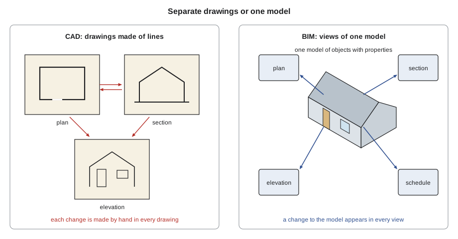
Computer-aided design began in the early 1960s. In 1963, Ivan Sutherland's Sketchpad, written at MIT, let a user draw on a screen with a light pen and showed that a drawing could be a structure of linked objects rather than a set of marks. Through the 1970s, researchers such as Charles Eastman at Carnegie Mellon described building description systems in which a building was a database of elements, an idea very close to what we now call BIM. In 1982 Autodesk released AutoCAD for personal computers, and over the next two decades 2D CAD replaced the drafting board in most offices. The drawings looked the same as hand drawings, and so did the way they were organized: separate plans, sections and elevations, each drawn and revised independently.
The object-based approach reached architects in the 1980s and 1990s. Graphisoft in Hungary released ArchiCAD in 1987, built around a virtual building rather than a set of drawings. Revit, written by a small company in Massachusetts, appeared in 2000 and was bought by Autodesk in 2002; its central idea was that every view is a live view of one model, so a change made anywhere appears everywhere. In parallel, free-form modelers such as Rhino, first released in 1998, gave designers precise control over curved surfaces, and the Guggenheim Museum in Bilbao, completed in 1997, showed what aerospace software could do in architecture. The term building information modeling became widespread in the early 2000s, and since then it has become the normal way to document medium and large buildings in the United States and much of the world.
Families of digital tools
The software used in practice falls into a few families. Most offices use several, and the boundaries between them blur as products add features.
| Family | What it does | Common examples |
|---|---|---|
| 2D CAD | Precise lines, arcs and text; drawings as sets of geometry on layers | AutoCAD, BricsCAD, DraftSight |
| Surface and solid modelers | Free-form and precise 3D geometry for design and fabrication | Rhino, SketchUp, Blender, form-Z |
| BIM authoring | Building objects with properties, coordinated drawings and schedules | Revit, Archicad, Vectorworks Architect, Allplan, Tekla for structure |
| Visual programming | Geometry and data driven by rules and parameters | Grasshopper for Rhino, Dynamo for Revit |
| Visualization | Rendering, animation and real-time walkthroughs | Enscape, Twinmotion, Lumion, V-Ray, D5 Render, Unreal Engine |
| Analysis | Energy, daylight, structure, airflow and carbon | Ladybug Tools, IES VE, Sefaira, structural analysis programs |
| Coordination and checking | Combining models, detecting clashes, checking rules | Navisworks, Solibri, BIMcollab, ACC Model Coordination |
| Common data environments | Storing, sharing and approving project information | Autodesk Construction Cloud, Trimble Connect, BIMcloud, Speckle |
Two cautions apply to any list like this. First, products change quickly. Revit 2027, released in the spring of 2026, added rule-based numbering, walls that can be hosted on other walls, and a technical preview of an AI assistant that can query a model and create views and schedules on request. Graphisoft is replacing the first version of its AI Visualizer for Archicad with newer versions tied to Archicad 29 and the coming Archicad 30. By the time you graduate, some of the tools in the table will have new names, new owners or new competitors. Second, the family matters more than the brand. If you understand what a BIM authoring tool does, what a visual programming tool does and why a coordination tool exists, you can learn a new product in weeks.
How offices choose and use tools
A practice chooses software for practical reasons: what its clients and consultants use, what its staff know, what the projects need, what it costs and how well it exchanges data with other programs. A small residential office may work entirely in one BIM program with a real-time renderer. A large firm doing hospitals and airports will have a BIM authoring standard, a coordination platform, a visual programming group and a team that writes custom tools. A design-led studio may do its early design in Rhino and Grasshopper and move to BIM only for documentation.
Whatever the tools, the office will have standards: a template file with predefined views, line weights, text styles and title blocks; naming rules for files, views and sheets; a folder structure; rules for who may edit which part of the model; and a BIM execution plan for each project that sets out what will be modeled, by whom, to what level of detail, in which format and when. These standards are often more important to a new employee than the software itself. The fastest way to become useful in an office is to learn its standards and follow them exactly.
Formats and interoperability
Every program stores its work in its own native format, such as RVT for Revit, PLN for Archicad, 3DM for Rhino and SKP for SketchUp. Native files keep all the program's intelligence but can usually be opened only by that program, and often only by the same or a newer version. To exchange work with others, offices use exchange formats.
- DWG and DXF carry 2D and simple 3D CAD geometry. DXF, introduced by Autodesk in 1982, is a documented text format that many programs can read.
- IFC, the Industry Foundation Classes, is the open, international format for building information, maintained by buildingSMART. Its current version, IFC 4.3, was published as the international standard ISO 16739-1 in 2024 and extends IFC from buildings to roads, railways, bridges and ports.
- OBJ, FBX, glTF and USD carry meshes, materials and scenes for rendering, games and virtual reality.
- STL and 3MF carry triangle meshes for 3D printing; STEP and IGES carry precise solids and surfaces for manufacturing.
- PDF remains the format in which most drawings are issued, reviewed and signed.
Every exchange loses something. A Revit wall exported to DWG becomes lines; exported to IFC it stays a wall with properties, but some program-specific parameters may be lost or renamed. Good practice is to agree formats at the start of a project, test the exchange early with a small sample, and document what each party must deliver.
Managing files and versions
A building project produces thousands of files. Drawings are revised, models are updated daily and consultants send new versions every week. Without discipline, people work on outdated files, overwrite each other's work and issue drawings that do not match the model. Offices manage this with three habits. Files are named by a consistent rule, so that a name tells you the project, the author, the part of the building, the type of information and the number. Work is kept in a shared, backed-up location, not on a personal laptop. And information moves through clear states, from work in progress to shared for coordination to published for construction, a process described by the international standard ISO 19650 that you will study in lesson 10.
A common naming pattern, used in the national annex to ISO 19650 in the United Kingdom and adapted by many firms in North America, joins fields with hyphens: project, originator, volume or zone, level, type, role and number. In this course the boathouse model is named KPB-ELM-ZZ-ZZ-M3-A-0001: Kestrel Point boathouse, Elmhurst School, all zones, all levels, a 3D model, architecture, number one.
# Check file names against a simple project naming rule:
# project-originator-zone-level-type-role-number
import re
rule = re.compile(r"(KPB)-([A-Z]{3})-([A-Z0-9]{2})-([A-Z0-9]{2})-(M3|DR|SH|SC|RP)-([A-Z])-(\d{4})")
fields = ["project", "originator", "zone", "level", "type", "role", "number"]
names = ["KPB-ELM-ZZ-ZZ-M3-A-0001", "KPB-ELM-ZZ-01-DR-A-1001", "kpb_final_FINAL2", "KPB-ELM-ZZ-00-DR-S-2001"]
for n in names:
    m = rule.fullmatch(n)
    if m:
        parts = dict(zip(fields, m.groups()))
        print(f"{n:26s} ok   type={parts['type']} role={parts['role']} number={parts['number']}")
    else:
print(f"{n:26s} does not follow the rule")KPB-ELM-ZZ-ZZ-M3-A-0001 ok type=M3 role=A number=0001 KPB-ELM-ZZ-01-DR-A-1001 ok type=DR role=A number=1001 kpb_final_FINAL2 does not follow the rule KPB-ELM-ZZ-00-DR-S-2001 ok type=DR role=S number=2001
A name such as kpb_final_FINAL2 tells nobody anything, and every office has stories of the file that was not the final one after all. A rule that a script can check is a rule that people will actually follow.
Hardware, licenses and the cloud
BIM and rendering are demanding. A typical workstation for this course has a multi-core processor, at least 32 GB of memory, a dedicated graphics card and a fast solid-state drive; a second monitor is more useful than almost any other upgrade. Real-time rendering depends most on the graphics card, while large BIM models depend on memory and single-core processor speed. Most professional software is licensed by subscription, and the major vendors offer free educational licenses to students, with the condition that the work is not used commercially.
More and more of the work happens in the cloud. Models are stored and shared on a common data environment, several people can work on one model at once through worksharing or cloud collaboration, and some analysis and rendering run on remote servers. Platforms such as Speckle, which began as a research project at University College London, move geometry and data between programs as streams of objects rather than files. This makes collaboration easier, but it also means that an office must think about who owns the data, where it is stored, and what happens if a service changes or closes, as the Archicad AI Visualizer transition shows on a small scale.
Artificial intelligence in design tools
Since about 2023, AI has entered architectural software in three main ways. Image generators can turn a sketch, a massing model or a text prompt into a rendered image in seconds; they are useful for early mood studies but do not produce buildable geometry, and the images can contain details that make no sense. Assistants built into BIM programs, such as the technical preview in Revit 2027, answer questions about a model and automate routine tasks such as creating views, schedules or sheets. And generative design tools explore many options for a layout or massing against goals such as daylight, area or cost. In every case the architect remains responsible for the result. An AI tool can save hours on repetitive work, but it cannot know whether a stair meets the code or whether a detail will leak unless someone who does know checks it.
Worked problem
Choosing tools for the boathouse
Callum wants to design the Kestrel Point boathouse, about 24 × 16 ft with a 9:12 gable roof, produce a small set of drawings, render it for a review, and laser-cut a 1/4 in = 1 ft model. Which families of tools does he need?
Show solution
- Concept: sketches on paper or a tablet, then a quick massing in a surface modeler such as SketchUp or Rhino to test proportions.
- Design development and drawings: a BIM authoring tool, so the plan, sections, elevations and a door and window schedule all come from one model.
- Visualization: a real-time renderer linked to the BIM model, so that design changes appear in the renderings without re-exporting.
- Fabrication: export the walls and roof as flat outlines to the laser cutter, using DXF or the cutter's own software, with the material thickness and kerf taken into account.
Answer: Even a one-room building uses four families of tools. The skill is in moving cleanly between them and knowing which one is the source of truth: here, the BIM model.
Exercise 1: a tool map
This exercise takes about two hours.
- Choose a recent built project by a firm whose work you admire, ideally one that has published how it was designed.
- Research which tools were used at each stage: concept, design development, analysis, documentation, coordination, visualization and fabrication.
- Draw a tool map: a diagram with the stages along the bottom and the tools above, with arrows showing where information moved from one tool to another and in what format.
- Mark each arrow where information was probably lost or had to be rebuilt by hand.
- Deliverable: one sheet with the tool map and a paragraph on what the firm's workflow suggests about its priorities.
Self-critique checklist
- Have I named the family of each tool, not only the product?
- Have I identified which tool was the source of truth at each stage?
- Have I shown the formats used for each exchange?
- Have I marked where information was lost or rebuilt?
Common mistakes
MistakeThinking that learning one program is learning digital design.
InsteadPractice uses a chain of tools; the concepts of modeling, data and coordination carry from one program to the next.
MistakeKeeping project files on a personal laptop.
InsteadProject work belongs in a shared, backed-up location with clear names and versions.
MistakeAssuming exchange formats carry everything.
InsteadEvery export loses some information; test exchanges early and agree what each party will deliver.
MistakeTrusting an AI-generated image or answer without checking it.
InsteadAI tools are fast assistants; the architect is still responsible for every decision in the drawings.
MistakeIgnoring the office template and naming rules.
InsteadOffice standards are what make a model usable by the rest of the team.
Summary and key terms
- Digital tools serve the same purposes as drawing by hand: thinking, testing, describing and communicating a building.
- The history runs from Sketchpad in 1963 through 2D CAD in the 1980s to object-based BIM, which became widespread in the 2000s.
- Practice uses families of tools: 2D CAD, modelers, BIM authoring, visual programming, visualization, analysis, coordination and common data environments.
- Native formats keep a program's intelligence; exchange formats such as DWG, IFC, OBJ and STL let programs share work, with some loss.
- Consistent naming, shared storage and controlled information states keep a project's files trustworthy.
- AI tools can speed up routine tasks and early images, but the architect remains responsible for the result.
- CAD
- Computer-aided design or drafting: drawing with precise digital geometry.
- BIM
- Building information modeling: designing and documenting a building as a model of objects with properties, from which drawings and data are generated.
- Native format
- The file format a program uses for its own work, which keeps all of its features.
- IFC
- Industry Foundation Classes, the open international standard for exchanging building information (ISO 16739-1).
- BIM execution plan
- A project document that sets out what will be modeled, by whom, to what level of detail and in which formats.
- Common data environment
- A shared, controlled place where project information is stored, exchanged and approved.
Practice problems
Work each problem on paper first, then reveal the answer to check.
What was Sketchpad, and why does it matter to BIM?
Show answer
Ivan Sutherland's 1963 program at MIT; it treated a drawing as linked objects rather than marks, the idea behind object-based modeling.
Name the family of tool you would use to check a combined architectural and structural model for clashes.
Show answer
A coordination and checking tool, such as Navisworks or Solibri.
Why might a wall exported from a BIM program to DWG be less useful than one exported to IFC?
Show answer
In DWG it becomes lines; in IFC it remains a wall object with properties such as type, materials and fire rating.
Decode the file name KPB-ELM-ZZ-01-DR-A-1001.
Show answer
Kestrel Point boathouse, Elmhurst School, all zones, level 01, a drawing, architecture, number 1001.
Give one strength and one limitation of AI image generators in early design.
Show answer
They produce mood images very quickly, but they do not produce buildable geometry and may show impossible details.
Lesson quiz · 5 questions
Score 60% or more to complete this lesson.
Create a free account to save your progress, take quizzes and earn a certificate.