
ARCH-210 · Lesson 2 of 12 · 22 min
3D modeling
In the second week Professor Ferreira projects two models of the same curved canopy on the screen. One is smooth and sleek; the other looks faceted, like a cut gem. 'They are the same shape,' she says, 'but they are different kinds of geometry. The first is a NURBS surface, defined by mathematics. The second is a mesh of triangles, defined by points. If you send the first to a fabricator, they can cut it precisely. If you send the second, they will ask you why your canopy has three thousand flat facets.' Joon-ho, who has used Blender for years to make game scenery, admits that he has never thought of the difference. 'In a game,' he says, 'nobody has to build it.'
What 3D modeling is
A 3D model is a mathematical description of objects in space. Every program stores geometry as numbers: the coordinates of points, the equations or control points of curves and surfaces, and the way these are connected. When you orbit around a model, the program redraws it from a new viewpoint many times a second, but the model itself is a list of numbers, not a picture. This matters because the kind of geometry you choose decides what you can do with the model: whether it can be measured precisely, edited easily, rendered quickly, analyzed or fabricated.
Architects use 3D models for many purposes: to study massing and proportion, to test how light falls in a space, to coordinate a structure with the walls around it, to generate drawings, to calculate quantities, and to send geometry to machines that cut, mill or print. A model good for one purpose may be poor for another. An early massing model should be quick and rough. A fabrication model must be precise to a fraction of a millimeter. A rendering model needs good materials and lighting but can cheat on hidden parts.
Space, units and precision
Every model sits in a coordinate system with an origin and three axes, usually x to the east, y to the north and z up. Before modeling anything, set the units and the tolerance. Architects in the United States usually model in feet and inches; whatever the unit, the model should be at full size, one unit in the model equal to one real unit, not scaled down as a physical model would be. Scaling happens only when a drawing is printed or a physical model is cut.
The tolerance is the smallest distance the program treats as meaningful. Two points closer than the tolerance count as the same point. A tolerance of about 0.001 in is typical for building work. A model with tiny gaps between surfaces that should meet, or with edges a fraction of the tolerance long, causes trouble later, when surfaces will not join into a solid or a Boolean operation fails. Large coordinates also cause trouble: a model placed millions of units from the origin, as happens when a survey in real geographic coordinates is imported directly, loses precision and can display jittery edges. Most offices keep the project near the origin and record the relationship to the survey separately, as a shared or survey point.
Kinds of geometry
Modeling programs use four basic kinds of geometry. Most programs support more than one, and many problems in digital design come from not knowing which kind you are working with.
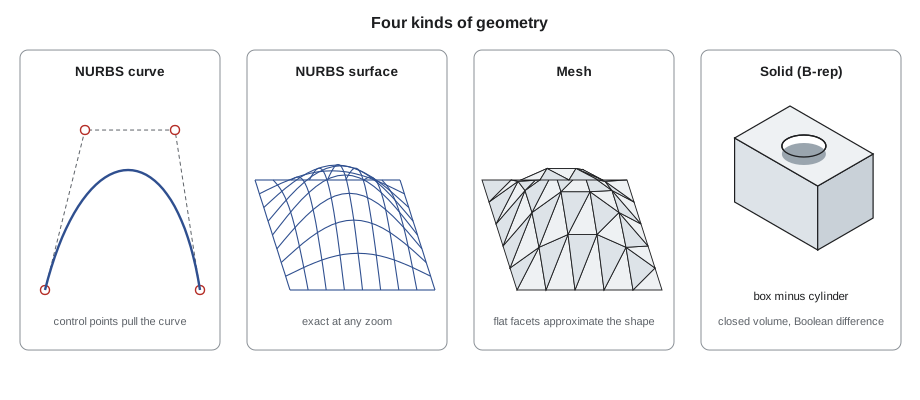
- Points and curves. Lines, arcs, circles and polylines are the simplest curves. Free-form curves are usually NURBS, non-uniform rational B-splines, defined by a degree, a set of control points, weights and a knot vector. The curve does not usually pass through its inner control points; it is pulled toward them, which is why moving one control point reshapes the curve smoothly. Bézier curves, developed in the French car industry in the 1960s by Pierre Bézier and Paul de Casteljau, are a special case.
- Surfaces. A NURBS surface is a curve swept in two directions, with a grid of control points. Surfaces are created by operations on curves: extrude a curve in a straight line, revolve it around an axis, loft through several curves, or sweep a profile along a path. Surfaces are exact: a NURBS cylinder is a true cylinder at any zoom.
- Meshes. A mesh is a set of vertices connected into flat faces, usually triangles or quadrilaterals. Meshes are simple and fast to display, so renderers, game engines, 3D printers and scanners use them. They approximate curved shapes with facets, so precision depends on how dense the mesh is. Subdivision modeling, common in Blender, starts with a coarse mesh and smooths it by repeatedly splitting faces.
- Solids. A solid is a closed, watertight volume. Most CAD solids are stored as a boundary representation, or B-rep: a set of surfaces joined along shared edges so that they enclose space with no gaps. Solids can be combined with Boolean operations: union adds two solids, difference subtracts one from another, and intersection keeps only the shared volume. BIM objects such as walls and slabs are solids, which is why you can cut a door opening into a wall.
| Geometry | Exact? | Good for | Poor for |
|---|---|---|---|
| NURBS curves and surfaces | Yes | Free-form design, fabrication, precise drawings | Very large scenes, real-time display |
| Meshes | Approximate | Rendering, games, 3D printing, scans, organic forms | Precise editing, clean drawings |
| Solids (B-rep) | Yes | Building elements, Boolean operations, volumes, BIM | Very free sculptural forms |
| Subdivision surfaces | Smooth limit of a mesh | Organic forms, quick sculpting | Precise dimensions without conversion |
Curves under the surface
Understanding how a free-form curve is built helps you control it. A cubic Bézier curve has four control points. De Casteljau's algorithm finds a point on the curve by interpolating between the control points again and again until only one point remains. The same idea, repeated, defines NURBS surfaces.
# De Casteljau's algorithm: a point on a cubic Bezier curve by repeated interpolation
def lerp(p, q, t):
    return (p[0] + (q[0] - p[0]) * t, p[1] + (q[1] - p[1]) * t)
def bezier(ctrl, t):
    pts = list(ctrl)
    while len(pts) > 1:
        pts = [lerp(pts[i], pts[i + 1], t) for i in range(len(pts) - 1)]
    return pts[0]
ctrl = [(0, 0), (2, 3), (6, 3), (8, 0)]   # a gentle arch, four control points
for t in (0, 0.25, 0.5, 0.75, 1):
    x, y = bezier(ctrl, t)
    print(f"t = {t:4.2f}  point = ({x:5.3f}, {y:5.3f})")
# the curve starts and ends on the end control points but only approaches the inner onest = 0.00 point = (0.000, 0.000) t = 0.25 point = (1.812, 1.688) t = 0.50 point = (4.000, 2.250) t = 0.75 point = (6.188, 1.688) t = 1.00 point = (8.000, 0.000)
The curve passes through the first and last control points and is tangent there to the control polygon, but it only approaches the inner points. Designers learn to place control points sparingly: a curve with too many control points is hard to edit and tends to wobble.
Modeling operations
Most modeling is done with a small set of operations. Extrusion pulls a closed curve into a prism, which is how most walls, slabs and massing blocks begin. Revolving a profile around an axis makes domes, columns and vases. Lofting stretches a surface through a series of section curves, useful for hulls, canopies and twisting towers. Sweeping drags a profile along a path, such as a handrail along a stair. Boolean operations add and subtract solids. Filleting and chamfering round or bevel edges. Arrays and transformations copy, move, rotate, scale and mirror objects, often in patterns.
Direct modelers such as SketchUp let you push and pull faces interactively; history-based modelers record each operation, so you can go back and change an early step and have the later steps update. History is powerful but fragile: if you delete an early curve, everything built on it may fail. Visual programming, covered in lesson 9, makes that history explicit as a graph that you design on purpose.
Meshes, solids and checking a model
A model that will be printed, analyzed or converted to a solid must be closed and consistent. A closed mesh with no holes and no edges shared by more than two faces is called manifold. For a simple closed mesh without holes through it, the number of vertices minus edges plus faces equals 2, a relationship discovered by Euler. The script below builds the boathouse massing as a closed triangle mesh and checks it, then computes its volume by adding up the signed volumes of tetrahedra formed by each triangle and the origin, the same method many programs use.
# A closed mesh of the boathouse massing: a box with a gable roof.
# Units: ft. The volume comes from the signed volumes of tetrahedra
# formed by each triangle and the origin.
L, W, H, R = 24, 16, 8, 14      # length, width, wall height, ridge height
v = [(0, 0, 0), (L, 0, 0), (L, W, 0), (0, W, 0),
     (0, 0, H), (L, 0, H), (L, W, H), (0, W, H),
     (0, W / 2, R), (L, W / 2, R)]
faces = [(0, 2, 1), (0, 3, 2),                      # floor
         (0, 1, 5), (0, 5, 4), (2, 3, 7), (2, 7, 6),  # long walls
         (1, 2, 6), (1, 6, 5), (3, 0, 4), (3, 4, 7),  # end walls
         (4, 5, 9), (4, 9, 8), (6, 7, 8), (6, 8, 9),  # roof planes
         (5, 6, 9), (7, 4, 8)]                        # gable triangles
def tet(a, b, c):
    (ax, ay, az), (bx, by, bz), (cx, cy, cz) = a, b, c
    return (ax * (by * cz - bz * cy) - ay * (bx * cz - bz * cx) + az * (bx * cy - by * cx)) / 6
vol = sum(tet(v[i], v[j], v[k]) for i, j, k in faces)
edges = {tuple(sorted(e)) for f in faces for e in ((f[0], f[1]), (f[1], f[2]), (f[2], f[0]))}
print("vertices", len(v), "edges", len(edges), "faces", len(faces))
print("Euler characteristic V - E + F =", len(v) - len(edges) + len(faces))
print(f"enclosed volume = {vol:.3f} ft^3")
print(f"check by formula = {L * W * H + 0.5 * W * (R - H) * L:.3f} ft^3")vertices 10 edges 24 faces 16 Euler characteristic V - E + F = 2 enclosed volume = 4224.000 ft^3 check by formula = 4224.000 ft^3
The two answers agree, which tells us the mesh is closed and its faces are all oriented the same way, outward. If one triangle were flipped, the volume would come out wrong; if one were missing, the Euler check would fail. Programs perform similar checks when they report a mesh as not closed or a solid as invalid.
Good modeling habits
Experienced modelers share a few habits. They model at full size in real units near the origin. They organize the model from the start, using layers, groups or components named so that someone else can understand them. They build with as little geometry as the purpose requires: a massing model needs no window mullions, and a detailed model does not need every screw. They snap to existing points and use exact dimensions rather than eyeballing. They avoid duplicate geometry, which doubles areas and confuses Boolean operations. They save versions at milestones rather than one file overwritten for weeks. And they check the model regularly for open edges, tiny gaps and inverted faces before those problems spread.
Massing models deserve special mention. Early in a design, a quick model of simple blocks answers big questions: how the building sits on the site, how tall it is compared with its neighbors, how its shadow falls, how much floor area it holds. These models should be fast and disposable. Students often spend too long making an early model beautiful and then resist changing it. Model to think, then throw it away and model again.
Worked problem
Massing the mixed-use building
The team must test two massings for the four-story building on Lake Street: a solid block 120 ft × 60 ft in plan and 50 ft tall, and the same block with a 20 ft courtyard cut through its middle on the upper three floors. What operations and checks are needed?
Show solution
- Draw the footprint as a closed rectangle and extrude it to full height to make a solid.
- For the second option, draw the courtyard rectangle on the second floor level and extrude it upward through the roof as a separate solid.
- Subtract the courtyard solid from the block with a Boolean difference; the result must still report as a closed, valid solid.
- Measure the volumes and the roof area of each option and compare the gross floor area by slicing at each floor level.
Answer: Simple solids and one Boolean operation answer the first design question in minutes, with exact areas and volumes to compare.
Exercise 2: three geometries, one object
This exercise takes about four hours.
- Model the Kestrel Point boathouse roof three ways: as two planar surfaces meeting at the ridge, as a single curved NURBS roof of the same width and peak height, and as a mesh made by converting the curved roof.
- Join the walls and the planar roof into a closed solid and report its volume; compare it with the hand calculation.
- Convert the curved roof to meshes of three densities and note how the file size and the appearance change.
- Cut a door opening into the solid wall with a Boolean difference.
- Deliverable: a sheet with views of each version, the volume check, and a short table comparing the geometry types for this object.
Self-critique checklist
- Is the model at full size, in real units, near the origin?
- Are the joined surfaces really closed, with no open edges?
- Can I explain which geometry type each part of my model uses and why?
- Is the model organized and named so that a classmate could open it and understand it?
Common mistakes
MistakeModeling at a reduced scale, as for a physical model.
InsteadModel at full size in real units; scale only when printing or cutting.
MistakeImporting a survey in real geographic coordinates and modeling far from the origin.
InsteadKeep the model near the origin and record the survey relationship separately to avoid precision errors.
MistakeSending a mesh to someone who needs exact geometry.
InsteadKeep the NURBS or solid original; meshes are approximations.
MistakeLeaving tiny gaps between surfaces that should meet.
InsteadSnap to points, join surfaces and check for open edges before going further.
MistakeSpending hours perfecting the first massing model.
InsteadEarly models are for thinking; make them fast and expect to replace them.
Summary and key terms
- A 3D model is a numerical description of geometry; the kind of geometry decides what the model can be used for.
- Set units and tolerance first, model at full size and keep the model near the origin.
- NURBS curves and surfaces are exact and smooth; meshes approximate with facets; solids are closed volumes that support Boolean operations.
- Extrude, revolve, loft, sweep and Boolean operations make most architectural forms.
- Closed, manifold geometry can be measured, printed and analyzed; checking for gaps and flipped faces saves trouble later.
- Massing models are quick tools for early decisions.
- NURBS
- Non-uniform rational B-splines: exact mathematical curves and surfaces controlled by points, weights and knots.
- Mesh
- A set of vertices joined into flat faces, usually triangles or quadrilaterals.
- B-rep
- Boundary representation: a solid stored as surfaces joined along shared edges to enclose a volume.
- Boolean operation
- Union, difference or intersection of solids.
- Tolerance
- The smallest distance the program treats as meaningful.
- Manifold
- A closed mesh in which every edge is shared by exactly two faces, enclosing a volume without holes.
Practice problems
Work each problem on paper first, then reveal the answer to check.
Why should a model be built at full size rather than at drawing scale?
Show answer
Measurements, quantities and exports are then correct in real units; scale is applied only when printing or fabricating.
What problem can arise when a model is placed very far from the origin?
Show answer
Loss of numerical precision, causing jittery display and inaccurate geometry.
Why do renderers and 3D printers use meshes?
Show answer
Meshes are simple flat facets that are fast to display and easy to slice into layers.
What does a Boolean difference do?
Show answer
It subtracts one solid from another, such as cutting an opening into a wall.
A closed mesh has 10 vertices and 16 triangular faces. How many edges should it have if it is a simple closed surface?
Show answer
From V − E + F = 2, E = 10 + 16 − 2 = 24 edges.
Lesson quiz · 5 questions
Score 60% or more to complete this lesson.
Create a free account to save your progress, take quizzes and earn a certificate.