
ARCH-210 · Lesson 4 of 12 · 22 min
Modeling walls, floors and roofs
By the fourth week the class has a template file with levels, grids and a title block, and Professor Ferreira sets the first real modeling task: the walls, floor and roof of the Kestrel Point boathouse, now designed as the heated winter warming hut that the class detailed in ARCH-130. Callum starts by drawing the walls as four plain boxes and gets a model in ten minutes. Then he cuts a section, and the boxes are solid gray with no layers, the corners overlap, and the walls stop at a flat height while the roof floats above. 'That is a 3D sketch,' Professor Ferreira says, looking over his shoulder. 'A BIM wall is a construction assembly that knows its layers, how it joins its neighbors, what it sits on and what it stops under. Model it the way it will be built and the drawings will almost draw themselves.'
Walls as assemblies
In a BIM program, a wall is defined by a wall type: a named assembly of layers, each with a material, a thickness and a function. A typical function list includes structure, substrate, thermal or air layer, membrane, and finish. The program uses these functions to decide how layers join at corners and around openings, which layers wrap at the ends of a wall, and how the wall is hatched when it is cut in plan or section. The core is the part of the wall between the core boundaries, usually the structural layers; finishes and cladding sit outside it.
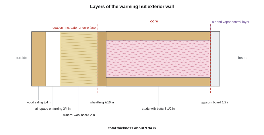
The layers of the warming-hut wall come straight from the assembly the class designed in ARCH-130. Setting them up in the wall type means that every plan and section shows the correct build-up, that the total thickness is right, and that later the program can report the area of each material.
# A compound wall type: layers from outside to inside (in).
layers = [("wood siding", 0.75, False), ("air space on furring", 0.75, False), ("mineral wool board", 2.0, False), ("sheathing", 0.4375, True), ("studs 2x6 with batts", 5.5, True), ("air and vapor control layer", 0.0, False), ("gypsum board", 0.5, False)]
total = sum(t for _, t, _ in layers)
core = [i for i, (_, _, c) in enumerate(layers) if c]
outside_to_core = sum(t for _, t, _ in layers[:core[0]])
pos = 0.0
for name, t, c in layers:
    print(f"{name:28s} {t:7.3f}  from outside face {pos:7.3f} to {pos + t:7.3f}{'  core' if c else ''}")
    pos += t
print(f"total thickness {total:.3f} in")
print(f"core boundary, exterior side, is {outside_to_core:.3f} in inside the outer face")wood siding 0.750 from outside face 0.000 to 0.750 air space on furring 0.750 from outside face 0.750 to 1.500 mineral wool board 2.000 from outside face 1.500 to 3.500 sheathing 0.438 from outside face 3.500 to 3.938 core studs 2x6 with batts 5.500 from outside face 3.938 to 9.438 core air and vapor control layer 0.000 from outside face 9.438 to 9.438 gypsum board 0.500 from outside face 9.438 to 9.938 total thickness 9.938 in core boundary, exterior side, is 3.500 in inside the outer face
Membranes have no thickness in the model but still appear as layers, so they show in sections and in material takeoffs. The core boundary on the exterior side sits behind the cladding and exterior insulation, which matters when you dimension the building: most offices dimension to the face of structure or the face of sheathing, not to the face of siding.
Location lines, joins and heights
Every wall has a location line, the line you draw when you place it: the wall's center line, a finish face or a core face. The choice matters when a wall type changes. If the location line is the exterior face of the core, swapping a 2x6 stud for a 2x4 stud keeps the outside of the structure where it is and moves the inside face; if the location line is the center line, both faces move. For exterior walls, offices usually use the exterior core face, because that line is fixed by the structure and the foundation below.
Where walls meet, the program cleans up the joins, trimming layers so that the corner reads correctly in plan. Butt joins, mitered joins and square-off joins give different results, and walls of different types, such as an exterior wall meeting an interior partition, need their priorities set so that the partition stops at the inside face of the exterior wall rather than cutting through its insulation. Checking every corner in a plan view at a large scale, early, saves hours later.
Walls have a base and a top. The base is attached to a level, with an offset if needed; the top is either a fixed height, another level, or attached to a roof or floor above. A wall whose top is attached to the roof follows the roof slope, so gable walls fill the triangle under the roof without separate geometry. In a multi-story building, walls usually run from level to level, so that each floor can be scheduled and changed separately, and cladding layers that run past slab edges are modeled as separate walls or as layers that extend.
Openings and wall-hosted elements
Doors and windows are hosted by walls. Placing a door cuts its opening in every layer of the wall and adds the door's own geometry and frame. The rough opening, the head and sill heights, and the way the wall's layers wrap into the opening are set in the door or window family and the wall type. Openings that are not doors or windows, such as a passage through a partition or a duct penetration, are made with an opening tool that cuts the wall without adding a component. Avoid cutting openings with in-place voids or edited profiles unless there is no other way, because those openings do not appear in schedules and are easily lost.
Floors and slabs
Floors are modeled like walls but horizontally: a floor type has layers from top to bottom, such as finish, underlayment, structural deck or slab, insulation and ceiling. The floor is drawn as a closed boundary in plan, usually by picking walls, and it can be attached to the walls so that it updates when they move. The thickness grows downward from the level, so the top of the floor sits at the level and its structure hangs below, which is the convention most drawings expect. Floors can be sloped, either uniformly with a slope arrow or locally to drains, and they can be edited point by point for drainage falls on roofs and showers.
In the mixed-use building on Lake Street, the two lower floors are concrete slabs and the upper floors are wood frame with a concrete topping. In the model, each is a different floor type. The concrete podium slab also has a slab edge, a profile swept along its perimeter to show a thickened edge or a drip, and penetrations for the shafts, cut with shaft openings that pass through several floors at once so they stay aligned.
A structural engineer will usually model the structural slabs in a separate structural model. The architect then models only the finish layers, or keeps an architectural slab for drawings and coordinates it with the structural one. Agreeing which discipline models which part, and avoiding two slabs in the same place, is one of the first items in a BIM execution plan.
Roofs
Roofs can be modeled in two main ways. A footprint roof is drawn as a plan boundary, usually by picking the exterior walls with an overhang, and each edge is given a slope or left flat. Edges with a slope become eaves; edges without one become gables. Changing a slope or an overhang regenerates the roof. An extruded roof is made by drawing a profile in elevation or section and extruding it along the building, which suits curved or unusual profiles. Low-slope roofs are usually modeled as floors or roofs with tapered insulation layers, with the slope achieved by editing points to drains.
Like walls and floors, roofs have types with layers: shingles or metal, underlayment, sheathing, structure, insulation and ceiling. A roof can be modeled as a simple assembly with structure as a layer, or with separate rafters or trusses modeled by the structural team or with framing tools. Fascia, soffits and gutters are added as sweeps along the roof edges.
# Gable roof by footprint and slope: area of roof surface including overhangs (ft)
import math
L, W, ovh = 24, 16, 1.5          # building length, width, overhang on every side
rise, run = 9, 12            # slope as rise over run
plan = (L + 2 * ovh) * (W + 2 * ovh)
factor = math.sqrt(1 + (rise / run) ** 2)
angle = math.degrees(math.atan(rise / run))
print(f"plan area of roof   {plan:8.2f} ft2")
print(f"slope factor        {factor:8.3f}  (angle {angle:.1f} degrees)")
print(f"surface area        {plan * factor:8.2f} ft2")
print(f"rafter length, wall face to ridge {(W / 2) * factor:.3f} ft plus {ovh * factor:.3f} ft of overhang")plan area of roof 513.00 ft2 slope factor 1.250 (angle 36.9 degrees) surface area 641.25 ft2 rafter length, wall face to ridge 10.000 ft plus 1.875 ft of overhang
The BIM program reports the same surface area as a property of the roof, which is how roofing quantities are estimated. If the hand calculation and the model disagree, something in the model, often an overhang or a slope, is not what you think it is.
Curtain walls and other special elements
Curtain walls are walls of a special kind: a grid of mullions with panels or glass between them. In BIM they are modeled as wall types whose grid spacing, mullion profiles and panel types are parameters, so that changing the spacing or swapping a panel updates the whole wall. Stairs, ramps and railings have their own tools with rules for riser height, tread depth and handrail extensions; using them, rather than modeling stairs as stacked boxes, lets the program check rise and run and produce stair schedules. Columns and beams are usually structural elements, placed on grids and levels and coordinated with the structural model.
Modeling in the order of construction
A clean model is built in roughly the order the building is: levels and grids, then foundations and structure, then floors, walls and roofs, then openings, then interior partitions, stairs and components. Elements should be modeled on the correct level and in the correct category, with the type that represents the real assembly, even early in the design, when the types may be generic placeholders with a sensible thickness. It is much easier to swap a generic 12 in exterior wall for a specific type later than to rebuild walls that were modeled as boxes.
Worked problem
Joining the warming hut corners
Wren models the four exterior walls of the warming hut with the wall type above, locating them on the exterior core face. In plan, the corners show the siding and the exterior insulation overlapping, and the gable walls stop at 8 ft under a roof that rises to 14 ft. What should she fix, and how?
Show solution
- Check that the walls were drawn in one direction, clockwise or counterclockwise consistently, so that the exterior face is outside on every wall; flip any that are reversed.
- Set the corner joins to butt or miter and confirm that the layers wrap consistently; the cladding and insulation should run continuously around the corner.
- Attach the tops of all four walls to the roof; the gable walls then fill the triangles under the roof planes automatically.
- Cut a section and a large-scale plan at a corner to confirm that the layers read as they will be built.
Answer: Most wall problems come from direction, join settings and unattached tops. A large-scale plan and section check catches them in minutes.
Exercise 4: the warming hut shell
This exercise takes about five hours.
- Set up levels for the floor, the top of the wall and the ridge, and a simple grid on the corners.
- Create the exterior wall type from ARCH-130 with every layer, and model the four exterior walls on the exterior core face.
- Model the floor as a floor type with its layers, and the roof as a footprint roof with 18 in overhangs on the eaves and 12 in on the gables.
- Attach the walls to the roof, place the door and windows, and add fascia and gutters as sweeps.
- Deliverable: a plan, two sections and a 3D view, plus a short report comparing your hand calculation of roof area with the model's value.
Self-critique checklist
- Does every wall, floor and roof use a type with real layers?
- Do the corners and the wall-to-roof joins read correctly in section?
- Are all elements on the correct level and in the correct category?
- Does the model's roof area match my hand calculation?
Common mistakes
MistakeModeling walls as generic boxes without layers.
InsteadUse wall types with real layers and functions, even early, so sections and quantities are correct.
MistakeLeaving wall tops at a fixed height under a sloped roof.
InsteadAttach walls to the roof so gables fill and later changes follow.
MistakeUsing the center line as the location line for exterior walls.
InsteadLocate exterior walls on the exterior core face so the structure stays fixed when types change.
MistakeCutting openings with voids that schedules cannot see.
InsteadUse door, window and opening tools so openings are hosted and counted.
MistakeModeling the same slab in both the architectural and structural models.
InsteadAgree who models what in the BIM execution plan.
Summary and key terms
- BIM walls, floors and roofs are assemblies of layers with materials, thicknesses and functions.
- The core boundaries and location line control how a wall is placed, dimensioned and changed.
- Wall joins, base and top constraints, and attachment to roofs and floors make the model behave like a building.
- Floors grow downward from their level; roofs are made by footprint and slope or by extrusion.
- Doors, windows and openings are hosted elements that cut their walls and appear in schedules.
- Model in the order of construction, with the right category and level for every element.
- Wall type
- A named assembly of layers defining a wall's construction.
- Core boundary
- The boundary between the structural core of a wall or floor and its finishes or cladding.
- Location line
- The line along which a wall is placed and which stays fixed when its type changes.
- Footprint roof
- A roof generated from a plan boundary with a slope set for each edge.
- Sweep
- A profile run along a path, used for fascia, gutters, slab edges and trim.
- Hosted element
- An element, such as a door or window, that depends on another element, such as a wall.
Practice problems
Work each problem on paper first, then reveal the answer to check.
Why should an exterior wall's location line usually be its exterior core face?
Show answer
That face is fixed by the structure and foundation, so changing the wall type does not move the building outline.
A roof has a 9:12 slope. What is the slope factor that converts plan area to surface area?
Show answer
√(1 + 0.75²) = 1.25.
What happens to a gable wall when its top is attached to the roof?
Show answer
It extends up to follow the roof planes, filling the triangle under the gable.
Why are walls in a multi-story building usually modeled level by level?
Show answer
So each floor's walls can be changed, scheduled and coordinated separately.
Name two ways to model a roof in BIM.
Show answer
By footprint, with slopes on its edges, and by extrusion of a profile.
Lesson quiz · 5 questions
Score 60% or more to complete this lesson.
Create a free account to save your progress, take quizzes and earn a certificate.