
WLD-330 · Lesson 8 of 12 · 16 min
Surface NDE: penetrant and magnetic particle
Some cracks are too fine to see. A hydrogen crack at the toe of a fillet on thick plate may be a few hundredths of a millimetre wide, and a fatigue crack starting from a weld toe on a crane runway is even finer. The two oldest non-destructive methods for finding them, liquid penetrant testing and magnetic particle testing, make them visible by drawing a coloured or fluorescent line across the surface where the crack is. Annika Sorensen, the NDE technician Hartwell brings in for its pressure work, spends a day in the shop with Devon's class and lets each apprentice run both methods on test plates with known cracks. She makes one point before anyone touches a can: these are surface methods, and they find only what reaches the surface or, for magnetic particle testing, lies just under it.
Who may do the work
Non-destructive testing that counts for code acceptance must be done by people certified for the method and level. In Canada, NDT personnel are certified by Natural Resources Canada's certification body under CAN/CGSB-48.9712, which is the Canadian adoption of ISO 9712. The certification is central, by examination, at Levels 1, 2 and 3 for each method; a Level 2 can set up equipment, carry out and interpret tests to written procedures and report results, and a Level 3 can write procedures and take technical responsibility. Annika holds Level 2 in magnetic particle, penetrant and ultrasonic testing. Apprentices can learn the methods and help, but a code examination is signed by a certified technician.
The method itself is controlled by a written procedure that names the materials, the surface preparation, the times and temperatures, the lighting and the acceptance criteria, and that refers to the standard the code calls up, such as ASME Section V for pressure work or the inspection clause and annexes of the structural code. Annika's procedures are approved by her company's Level 3 and accepted by Hartwell's client before use.
How liquid penetrant testing works
Penetrant testing relies on capillary action. A thin, brightly coloured or fluorescent liquid is applied to a clean surface and left long enough to be drawn into any open discontinuity. The excess is removed from the surface without washing the penetrant out of the discontinuities. A developer, a thin white coating, is then applied; it draws the penetrant back out of the discontinuities and spreads it into a visible indication. A crack shows as a line, porosity as dots, and lack of fusion at the surface as a line along the toe. The method works on any non-porous material, including stainless steel and aluminum, which is why Hartwell uses it on the Coldwater injection lines.
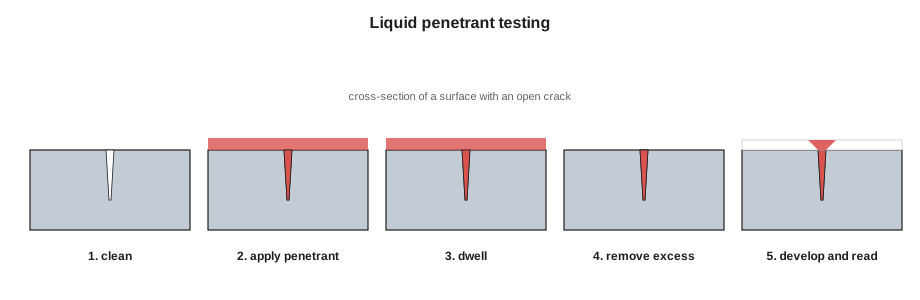
Each step can ruin the test if it is done badly. The surface must be clean, dry and free of paint, oil, scale and spatter, and it must not be smeared shut by heavy grinding or shot blasting, which can close a crack. The penetrant must stay on long enough, its dwell time, and the surface must be within the temperature range in the procedure. Excess penetrant is removed by wiping with a cloth lightly dampened with cleaner, never by spraying cleaner directly on the part, which washes penetrant out of shallow cracks. The developer is applied thin and even, and the part is inspected after the development time in good light.
ASME Section V sets the frame most procedures use: the part and penetrant within about 5 to 52 °C (40 to 125 °F), dwell times of several minutes depending on the material and the kind of discontinuity sought, and a development time of at least ten minutes before interpretation. Colour-contrast penetrant is read under white light of at least about 1,000 lux (100 foot-candles); fluorescent penetrant is read in a darkened area under ultraviolet light of the intensity the procedure states, after the inspector's eyes have adjusted to the dark. Outside the normal temperature range, a procedure qualified at that temperature is needed.
# Liquid penetrant timing check (procedure values of the kind ASME Section V frames; Annika's procedure governs)
T_MIN, T_MAX = 5, 52          # normal temperature range, deg C
DWELL = {'carbon steel weld': 10, 'stainless weld': 10, 'aluminum casting': 5}   # minutes, example values
DEV_MIN = 10                           # minutes of development before reading

tests = [
    # item, material, surface temperature, penetrant time, development time
    ('CI-117 repair', 'stainless weld', 18, 12, 15),
    ('lug toe BF-17', 'carbon steel weld', 22, 10, 12),
    ('tank weld', 'aluminum casting', 20, 3, 10),
    ('outdoor tie-in', 'carbon steel weld', -6, 15, 20),
]
for item, mat, temp, pen, dev in tests:
    faults = []
    if not T_MIN <= temp <= T_MAX:
        faults.append(f'surface {temp} deg C outside range: needs a procedure qualified for it')
    if pen < DWELL[mat]:
        faults.append(f'dwell {pen} min below {DWELL[mat]} min')
    if dev < DEV_MIN:
        faults.append(f'development {dev} min below {DEV_MIN} min')
print(f"{item:<16} {'valid test' if not faults else 'INVALID: ' + '; '.join(faults)}")CI-117 repair valid test lug toe BF-17 valid test tank weld INVALID: dwell 3 min below 5 min outdoor tie-in INVALID: surface -6 deg C outside range: needs a procedure qualified for it
Two of the four tests are invalid: the aluminum part did not get enough penetrant time, and the outdoor tie-in was tested on a surface far below the normal range, where the penetrant thickens and does not enter fine cracks. Neither result can be used, pass or fail; the tests must be repeated correctly. The dwell times in the program are example values; Annika's written procedure sets the ones she uses.
How magnetic particle testing works
Magnetic particle testing works only on ferromagnetic materials, which means carbon and low-alloy steels but not austenitic stainless steel or aluminum. The part is magnetized, and where a crack or other discontinuity interrupts the magnetic field at or near the surface, the field leaks out of the part. Fine iron particles, dry powder or particles suspended in a liquid, are applied and gather at the leakage field, building a visible line over the discontinuity. Visible particles, often red or grey on a thin white contrast paint, are read in white light; fluorescent particles are read under ultraviolet light in the dark and show fine cracks more clearly.
The direction of the field matters. A discontinuity shows best when it lies across the field lines and hardly at all when it lies along them. With a yoke, a U-shaped electromagnet placed across the weld, the field runs between the poles, so cracks parallel to the line between the poles are missed. Every area must therefore be tested twice, with the yoke turned roughly 90 degrees between the two placements, so that cracks in any direction are found. Annika's habit is to examine each area in two directions and overlap each placement with the last.
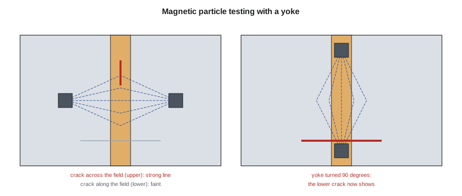
The equipment is checked before use. An alternating current yoke must lift a test weight of about 4.5 kg (10 lb) at its maximum pole spacing, and a direct current yoke one of about 18 kg (40 lb), because a yoke that cannot lift the weight may not magnetize the part strongly enough. The field direction and adequacy can also be checked with a field indicator or shims with built-in artificial flaws. Lighting is checked with a light meter, and the particles, if wet, are checked for concentration.
# Yoke and placement check before magnetic particle testing (lift test values as in ASME Section V)
LIFT_REQ = {'AC': 4.5, 'DC': 18}   # kg at maximum pole spacing
yokes = [('yoke 1', 'AC', 5.0), ('yoke 2', 'AC', 4.0), ('yoke 3', 'DC', 20)]
for name, kind, lifted in yokes:
    print(f"{name}: {kind} lifted {lifted} kg, needs {LIFT_REQ[kind]} -> {'in service' if lifted >= LIFT_REQ[kind] else 'tag out'}")

# A weld of a given length examined with a given pole spacing: placements needed in two directions
import math
weld_len, spacing, overlap = 1200, 150, 25
step = spacing - overlap
per_direction = math.ceil((weld_len - spacing) / step) + 1
print(f"weld {weld_len} mm with {spacing} mm spacing: {per_direction} placements each way, {2 * per_direction} in all")yoke 1: AC lifted 5.0 kg, needs 4.5 -> in service yoke 2: AC lifted 4.0 kg, needs 4.5 -> tag out yoke 3: DC lifted 20 kg, needs 18 -> in service weld 1200 mm with 150 mm spacing: 10 placements each way, 20 in all
Yoke 2 fails its lift test and is tagged out until it is repaired. For a girder flange weld of the given length, the program counts the yoke placements needed in each direction with the overlap Annika uses, and doubles the number for the second direction. Planning the placements tells the inspector how long the test will take and makes it easy to check that nothing was skipped.
Choosing between the methods
| Point | Penetrant testing | Magnetic particle testing |
|---|---|---|
| Materials | Any non-porous material | Ferromagnetic steels only |
| Finds | Discontinuities open to the surface | Surface and slightly subsurface discontinuities |
| Surface preparation | Very clean, not smeared shut | Clean; thin coatings may be tolerated by procedure |
| Speed | Slower, with dwell and development times | Faster on steel |
| Sensitivity to fine cracks | Good if clean and timed correctly | Very good across the field direction |
| Typical use at Hartwell | Stainless and aluminum, excavations on stainless | Fillet toes on thick steel, gouged excavations, crane and bridge welds |
On steel, magnetic particle testing is usually preferred because it is faster and finds slightly subsurface discontinuities as well as surface ones. On stainless steel and aluminum, penetrant testing is the only choice of the two. Both are used on back-gouged roots and repair excavations to confirm that a defect has been removed before rewelding, and both are used after welding, sometimes after a waiting period on thick, high-strength steel so that delayed hydrogen cracking has time to appear.
Interpreting indications
Not every indication is a defect, and not every line is a crack. Relevant indications come from real discontinuities. Non-relevant indications come from the geometry or the magnetization: particles gather at a sharp change of section, at the edge of the weld cap, at a boundary between metals of different magnetic properties, or along scratches. False indications come from poor practice, such as penetrant left on the surface or particles trapped in rough spatter. The technician evaluates each indication, removes and re-tests doubtful ones, and records relevant ones by type, location and length.
Acceptance criteria for surface methods usually distinguish linear indications, longer than about three times their width, from rounded ones. Linear indications from cracks and lack of fusion are generally rejected; rounded indications are limited by size and spacing. The structural codes' criteria for magnetic particle testing follow the visual criteria for the weld category, and the piping and pressure codes give their own. A rejected indication is marked for repair, and after repair the area is tested again by the same method.
Cleaning up and records
After the test the part is cleaned of penetrant, developer, contrast paint or particles, especially where coating will follow or where residue could cause corrosion. Stainless steel and nickel alloys need penetrant materials with low halogen and sulphur content so that residues do not cause corrosion later. The report records the procedure, the materials and their batch numbers, the equipment and its checks, the surface condition, the times and temperatures, the indications found, the evaluation against the criteria and the technician's name, certification level and signature.
Other surface and near-surface methods
Two more methods sometimes appear on Hartwell's jobs. Eddy current testing passes an alternating magnetic field from a coil into a conductive material and measures the small currents it induces; cracks and changes in thickness disturb those currents. It is used to find surface cracks through thin coatings without removing them, for example on painted bridge welds during in-service inspection, and to inspect heat exchanger tubes from the inside. Alternating current field measurement is a related method used offshore and on structures to find and size surface cracks through coatings. Both need certified technicians and procedures, and both are mostly used for inspection in service rather than during fabrication.
Devon also learns why surface methods are often specified after a waiting period on thick, high-strength welds. Hydrogen cracks can appear hours or even days after welding, so a magnetic particle test made while the weld is still warm may show nothing that will be there tomorrow. The specification for the Riverside splices calls for magnetic particle testing no sooner than a set time after welding, and Annika's reports record the time each weld was completed and tested.
Common mistakes
MistakeSpraying cleaner straight onto a penetrant test area.
InsteadWipe with a lightly dampened cloth so penetrant stays in the discontinuities.
MistakeUsing magnetic particle testing on austenitic stainless steel.
InsteadIt is not ferromagnetic; use penetrant testing.
MistakePlacing the yoke in one direction only.
InsteadTest each area in two directions roughly 90 degrees apart.
MistakeSkipping the yoke lift test.
InsteadCheck the lift each shift or as the procedure requires, and tag out yokes that fail.
MistakeGrinding heavily just before penetrant testing.
InsteadHeavy grinding can smear cracks shut; prepare by the procedure's method.
Summary and key terms
- Penetrant and magnetic particle testing find surface discontinuities; magnetic particle testing also finds some just below the surface.
- Certified technicians perform and sign code examinations to written procedures.
- Penetrant testing needs a clean surface, the right temperature, dwell and development times, and careful removal of excess.
- Magnetic particle testing needs a ferromagnetic part, a checked yoke and two directions of field.
- Indications are evaluated as relevant, non-relevant or false, and linear ones are treated strictly.
- Reports record materials, equipment checks, conditions, indications and the technician.
- Liquid penetrant testing
- A surface method in which a liquid drawn into discontinuities is brought out by a developer.
- Dwell time
- The time penetrant stays on the surface before excess is removed.
- Magnetic particle testing
- A method that shows leakage fields at discontinuities in a magnetized ferromagnetic part.
- Yoke
- A portable electromagnet used to magnetize a local area for magnetic particle testing.
- Lift test
- A check that a yoke can lift a standard weight at its maximum pole spacing.
- Linear indication
- An indication much longer than it is wide, treated as a possible crack or lack of fusion.
Practice problems
Work each problem on paper first, then reveal the answer to check.
Which surface method can be used on the stainless injection lines?
Show answer
Liquid penetrant testing.
An AC yoke lifts 4.0 kg at maximum spacing. Can it be used?
Show answer
No; it must lift about 4.5 kg.
Why must each area be tested in two directions with a yoke?
Show answer
Cracks along the field lines barely show; turning the yoke reveals them.
Lesson quiz · 5 questions
Score 60% or more to complete this lesson.
Create a free account to save your progress, take quizzes and earn a certificate.