
WLD-330 · Lesson 6 of 12 · 17 min
Visual inspection criteria and gauges
Most welds are accepted or rejected by eye. Radiography and ultrasonics get the attention, but on a structural job every weld is visually inspected and only a fraction gets any other test, and on pressure work visual inspection comes before every other method. Lucia calls visual inspection the cheapest test that finds the most defects. For two weeks Devon follows her on her rounds with a gauge kit, a flashlight, a mirror and a clipboard, and inspects the welds she inspects before she tells him what she found. By the end of the first week his reject list matches hers on most welds; by the end of the second it matches on all but one, a short end return on a gusset that he had not looked for.
Before, during and after welding
Good visual inspection starts before the arc is struck. Before welding the inspector checks the material and its markings against the drawing and mill certificate, the joint preparation, fit-up and root opening against the procedure, cleanliness, the welder's qualification, the procedure posted at the station and the condition of the equipment and consumables. During welding the inspector checks preheat and interpass temperature, the current and voltage against the procedure ranges, the root pass, back-gouging, cleaning between passes and the sequence. After welding the inspector checks the finished size, profile and surface against the acceptance criteria, and marks or records the result.
Most defects that radiography finds could have been prevented by inspection before and during welding. A root opening that is too tight will give incomplete penetration; a bevel with mill scale will give lack of fusion; an electrode left out of the oven will give porosity or hydrogen cracking. Lucia spends more of her day at the fitting tables and booths than at finished welds, and the finished-weld inspection is quicker because of it.
| Stage | Inspector checks |
|---|---|
| Before welding | Material and markings, procedure, welder qualification, joint fit-up, cleanliness, consumables, equipment |
| During welding | Preheat and interpass, electrical settings, root pass, back-gouging, interpass cleaning, sequence |
| After welding | Size, length, profile, surface discontinuities, distortion, marking and records |
Conditions for visual inspection
A visual inspection is only as good as the light and the inspector's eyes. Pressure codes, through ASME Section V, require that for direct visual examination the eye be within about 600 mm (24 in) of the surface at an angle of at least 30 degrees, with at least about 1,000 lux (100 foot-candles) of light at the surface, checked with a light meter. Structural codes have similar expectations. Inspectors must pass a near-vision acuity test and often a colour perception test, repeated at set intervals. Remote visual inspection with mirrors, borescopes and cameras is allowed where the eye cannot reach, provided it can resolve what direct inspection would.
The surface must be clean enough to see. Slag must be removed, spatter that hides the toe cleaned off, and paint kept away until inspection is done. A weld painted before inspection may have to be blast-cleaned for the inspector, which costs more than waiting a day.
The inspector's tools
The visual inspector's kit is small. A fillet weld gauge checks leg size and convexity or concavity. A multipurpose gauge, often called a bridge cam gauge, measures undercut depth, reinforcement height, fillet throat, misalignment and bevel angle. A hi-lo gauge measures internal misalignment on pipe. A tape, a straightedge and a square check length, distortion and fit-up. A magnifier of low power helps judge a suspected crack. A mirror and flashlight see the back of a joint. Temperature-indicating crayons and a contact thermometer check preheat and interpass temperature. A clamp-on meter checks current at the arc. Each gauge has a correct way to use it, and readings taken the wrong way are worthless.
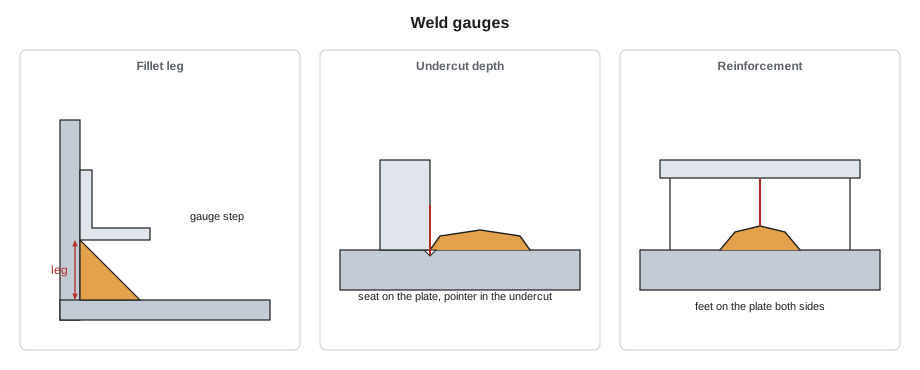
Lucia's rule for fillet gauges is to measure both legs and to check the throat, because a fillet can have both legs correct and still be concave enough to have a short throat. For undercut, the gauge must sit on the plate surface beside the weld and the pointer must reach the bottom of the undercut; measuring from the weld crown gives nonsense. For reinforcement on a groove weld, the gauge sits on the plate on both sides, and the height is read at the highest point of the crown.
What the visual criteria cover
Each code has a table of visual acceptance criteria. For structural steel, CSA W59 and AWS D1.1 both set limits for cracks, fusion, crater fill, weld profile, size, undercut and porosity, with separate limits for statically and cyclically loaded structures and for welds transverse or parallel to the main stress. For piping, B31.3 has its own table of limits by fluid service category. The broad pattern is the same everywhere: no cracks of any size; complete fusion between weld and base metal and between passes; craters filled to the full cross-section; profiles within limits; undersize allowed only for a short fraction of the length; undercut and porosity limited by depth, diameter and total length.
Some criteria are absolute and some are counted. A crack is rejectable at any length, and so is visible lack of fusion. Undercut is judged by depth, with a deeper limit allowed for short lengths in some codes. Porosity is judged by the size of each visible pore and the total diameter of pores in a given length of weld. Undersize fillets are allowed if the shortfall is small and covers only a small part of the length, and not at the ends of a weld where the stress is highest. Reinforcement on groove welds is limited in height, and in cyclically loaded structures welds may need to be ground flush.
| Discontinuity | Typical treatment in the criteria |
|---|---|
| Crack | Not permitted, any size |
| Lack of fusion visible at the surface | Not permitted |
| Crater not filled | Not permitted except outside the effective length |
| Undercut | Limited by depth, for example 0.8 mm (1/32 in) on thinner material, with stricter limits on cyclically loaded welds |
| Porosity | Limited by the sum of visible pore diameters in a given length |
| Undersize fillet | A small shortfall for a limited fraction of the length, not at the ends |
| Reinforcement and convexity | Limited height; flush grinding where the drawing or criteria require it |
Applying the criteria
# Visual inspection of a fillet weld against criteria of the kind the codes use (illustrative limits)
U = 'mm'
LIMITS = {'undercut': 0.8, 'porosity_per_length': 10, 'length_for_porosity': 25,
          'undersize': 1.6, 'undersize_fraction': 0.10}
welds = [
    # id, required leg, measured legs along the weld, max undercut, pores (diameters) in worst length, crack?
    ('BF-12 gusset', 6, [6.5] * 18 + [5.5, 6.0], 0.5, [], False),
    ('BF-14 stiffener', 8, [8.5] * 15 + [7.0, 7.0, 7.5, 6.0, 8.0], 1.0, [1.0, 1.5], False),
    ('BF-17 lug', 10, [10.5] * 20, 0.3, [], True),
]
for wid, leg, legs, uc, pores, crack in welds:
    faults = []
    if crack:
        faults.append('crack')
    if uc > LIMITS['undercut']:
        faults.append(f'undercut {uc} {U}')
    if sum(pores) > LIMITS['porosity_per_length']:
        faults.append(f'porosity sum {round(sum(pores), 3)} {U} in {LIMITS["length_for_porosity"]} {U}')
    short = [m for m in legs if m < leg]
    if any(leg - m > LIMITS['undersize'] for m in short) or len(short) / len(legs) > LIMITS['undersize_fraction']:
        faults.append('undersize beyond the allowance')
print(f"{wid:<16} {'ACCEPT' if not faults else 'REJECT: ' + ', '.join(faults)}")BF-12 gusset ACCEPT BF-14 stiffener REJECT: undercut 1.0 mm, undersize beyond the allowance BF-17 lug REJECT: crack
The gusset weld passes: one reading is slightly short, but the shortfall is within the allowance and covers a small part of the length. The stiffener weld fails on undercut and on undersize, with one reading well below the required leg and too many short readings. The lug fails at once because of a crack, whatever the other readings say. The limits in the program are illustrative; Lucia's checklist takes the real values, and the conditions that go with them, from the edition the job names.
Fillet weld size and profile
Fillet welds are inspected for size and shape. The leg is measured on each member; the size of an unequal-leg fillet is the smaller leg unless the drawing specifies both. The throat is checked where the fillet is concave, because the leg gauge alone overstates a concave fillet's strength. Excessive convexity is limited because a humped fillet has a sharp notch at the toe and wastes metal. The ends of fillets are checked for full size and for end returns where the drawing calls for them. An intermittent fillet is checked for the length of each segment and the pitch between them.
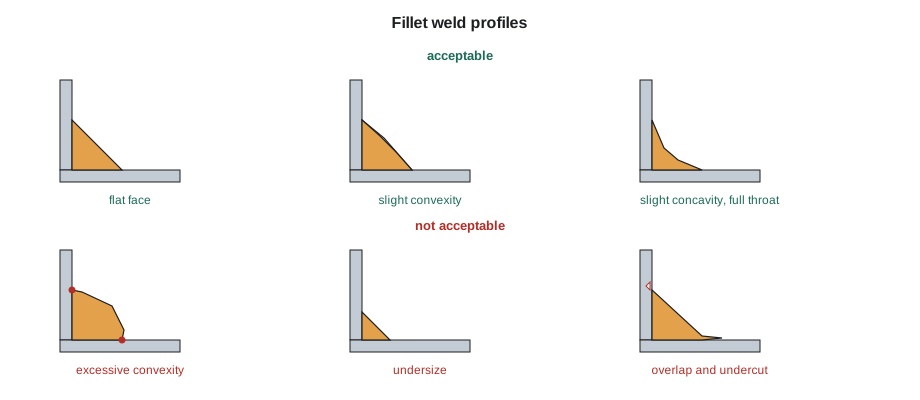
Groove welds are inspected for reinforcement, fill, undercut at the toes, root reinforcement and concavity where the root is visible, and for misalignment between the parts. Where the drawing calls for welds ground flush, the inspector checks that the grinding leaves no gouges and runs in the direction of stress. On pipe, the inspector checks the root from inside where it can be reached, with a mirror and light or a camera.
Recording and marking
An inspection that is not recorded did not happen, as far as an auditor is concerned. Lucia's records show the weld or assembly, the drawing and revision, the procedure, the welder, the inspection done, the criteria used, the result, and her signature and date. Welds that pass are marked with her stamp or a paint mark the quality manual defines; welds that fail are marked with the defect and its location so that the repair is made in the right place, and they go on the repair log. When the repair is done, the weld is inspected again and the record shows both inspections.
Marking needs care on stainless steel and on surfaces that will be painted or coated. Hartwell uses low-chloride markers on stainless and paint pens that the coating specification allows on structural steel. Stamps are kept off fatigue-sensitive areas of cyclically loaded members, and off thin-wall pipe.
Judgement and its limits
Visual criteria are written to be measurable, but they still need judgement. Is that line at the toe a crack or a shadow? Is a pore a pore or a spatter ball? Is the undercut continuous or a series of short marks? Lucia's rule is that when she is unsure, she cleans the area, looks again with a magnifier and better light, and if still unsure she asks for magnetic particle or penetrant testing, which lesson 8 covers. Devon's single disagreement with her in the second week was a short end return he had not looked for, not a measurement he had made wrong; inspection is as much about knowing where to look as about reading a gauge.
Distortion and dimensional checks
Visual inspection also covers what welding does to the shape of the part. Weld shrinkage pulls members out of square, bows long beams, closes the gaps in assemblies and changes overall lengths. The drawing gives tolerances, and the inspector checks them after welding with a tape, a straightedge, a square, a level or a string line, and on large assemblies with a total station. A flange that has tilted out of square on a girder, a base frame that has twisted so that it rocks on a flat floor, or a pipe spool whose flange holes no longer line up with the next spool can all be rejected even if every weld is perfect.
Lucia checks distortion at the same time as weld size because the two are linked: an oversize fillet adds shrinkage, and a welder who weaves too wide on one side of a joint pulls the part toward it. When she finds a dimensional problem, she records it on the same inspection sheet and Glen decides with Elena whether it can be corrected by heat straightening, by mechanical straightening or by cutting and refitting. Heat straightening on quenched and tempered or other heat-sensitive steels needs the engineer's approval and temperature control, so it is never done on the floor without a written instruction.
Devon learns to check the simple things first. A tape across the diagonals of a rectangular frame tells him in a minute whether it is square, and a string line along a beam shows any bow. These checks take less time than looking for undercut and catch problems that cost far more to fix after the part has been painted and shipped.
Common mistakes
MistakeInspecting only finished welds.
InsteadInspect before and during welding as well; most defects are prevented there.
MistakeReading undercut from the weld crown.
InsteadSeat the gauge on the plate beside the weld and reach the bottom of the undercut.
MistakeChecking only the legs of a concave fillet.
InsteadCheck the throat too; a concave fillet can be short of throat with full legs.
MistakeUsing statically loaded criteria everywhere.
InsteadUse the criteria for the loading category and stress direction.
MistakeLeaving inspection results unrecorded.
InsteadRecord the weld, criteria, result, inspector and date, and mark the weld.
Summary and key terms
- Visual inspection is done before, during and after welding.
- Light, distance, angle and clean surfaces are conditions for valid visual inspection.
- Fillet gauges, cam gauges, hi-lo gauges and thermometers are the main tools.
- Cracks and visible lack of fusion are never accepted; other discontinuities are limited by size and length.
- Criteria depend on the code, the loading category and the stress direction.
- Every inspection is recorded and every weld is marked as accepted or for repair.
- Visual inspection
- Examination of a weld and its preparation by eye, with gauges and lighting.
- Undercut
- A groove melted into the base metal at the toe and left unfilled.
- Reinforcement
- Weld metal above the surface of the plate on a groove weld.
- Convexity
- The height of a fillet face above a straight line between the toes.
- Throat
- The shortest distance from the root to the face of a fillet weld.
- Cam gauge
- A multipurpose gauge for undercut, reinforcement, throat and misalignment.
Practice problems
Work each problem on paper first, then reveal the answer to check.
What light level do pressure codes require for direct visual examination?
Show answer
At least about 1,000 lux at the surface.
A fillet has full legs but a concave face. What else must be checked?
Show answer
The throat.
Is a 2 mm crack at the toe of a statically loaded fillet acceptable?
Show answer
No; cracks are not accepted at any size.
Lesson quiz · 5 questions
Score 60% or more to complete this lesson.
Create a free account to save your progress, take quizzes and earn a certificate.