
RCDD-111 · Lesson 8 of 12 · 19 min
Cable tray, ladder rack and raceway
▶ Video coming soon A video version of this lesson is on the way.
Walking the corridor of an existing building on the college campus, Roz stops under an open ceiling and points up. Above the lights, a wire basket tray runs the length of the corridor, neatly filled. Next to it, someone has added a second route years later: bundles of cable tied to sprinkler pipes, draped over a duct and hung from the ceiling support wires. 'One of these was designed,' she says. 'The other one happened. Which one will still be working when the building is fifty?' Daniel knows the answer, and he also knows why the second one happened: the tray was too small, and there was nowhere else to go.
Cable tray, ladder rack and raceway are the open and semi-open pathways that carry most of the cable in a modern building. Tray and non-continuous supports such as J-hooks carry horizontal cable along corridors and through ceilings, ladder rack carries cable inside telecommunications rooms and equipment rooms, and surface raceway carries cable where walls cannot be opened. They are cheaper and far more flexible than conduit, and adding cable to them is easy, as long as the designer has left room. This lesson covers the types, the design rules and how to size them.
Why open pathways
Open pathways suit structured cabling well. Horizontal cables are numerous, light and frequently added, moved and removed during the life of a building, and an open pathway lets technicians do that without pulling cable through enclosed conduit. Open pathways also let heat escape from bundles of cables, which matters more now that power over Ethernet sends significant current through four-pair cables; tightly packed bundles in enclosed spaces run warmer, which reduces the current they can safely carry. The trade-off is protection: open pathways need accessible ceilings, cables rated for the spaces they pass through, and attention to support so that cables are not crushed or left sagging.
Types of cable tray
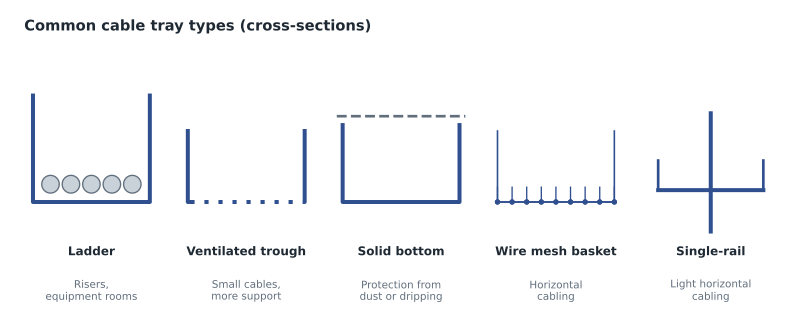
Cable tray comes in several forms, and the choice depends on the cable, the space and the loads. Industry standards for metallic cable tray systems, such as CSA C22.2 No. 126.1, harmonized with NEMA VE 1 in the United States, define construction, load ratings and testing.
| Type | Description | Typical use |
|---|---|---|
| Ladder tray | Two side rails joined by rungs, like a ladder | Heavy backbone and mixed cables in risers, equipment rooms and plant areas |
| Ventilated trough | A shallow channel with a perforated or slotted bottom | Smaller cables that need more continuous support than rungs provide |
| Solid-bottom tray | A channel with a continuous solid bottom, sometimes with a cover | Protection from dust, dripping or physical damage, at the cost of heat dissipation |
| Wire mesh (basket) tray | A grid of welded wires formed into a basket | Horizontal structured cabling in ceilings; easy to cut, turn and drop out of |
| Single-rail or centre-spine tray | Cantilevered arms on one central support | Light horizontal cabling where access from both sides helps |
| Channel tray | A narrow single channel | Small groups of cables branching off a main tray |
Design rules for cable tray
ANSI/TIA-569 and good practice give a handful of rules for telecommunications cable tray. Fill should be limited so that cables are not crushed, can be added and removed, and can shed heat: a common guideline is to fill no more than half the usable cross-section of the tray, and to keep the depth of cable to no more than about 150 mm, regardless of how deep the tray is, because cables at the bottom of a deep pile are crushed and impossible to remove. Trays should be sized for the cable expected at the end of the planning period, not today's count.
Access is the second rule. A tray that cannot be reached cannot be used. Common practice calls for about 300 mm of clear space above the tray for placing cables, and clear access along at least one side. Trays must not be buried above fixed ceilings, boxed in by ducts or run where sprinkler pipes or light fixtures block them. The coordination lesson returns to this, because ceiling spaces are crowded and the ICT designer must claim the tray's space early.
Support and loading come next. Trays are supported at intervals and in ways that the manufacturer specifies for the load, and the load includes the cable, the tray and any future cable. Long spans need heavier trays or more supports. Turns, tees, drops and changes in elevation should use manufactured fittings or approved field cuts, and they must keep the bend radius of the cables, especially fibre and large backbone cables. Waterfalls or drop-outs where cables leave a tray prevent cables from being bent over a sharp edge.
Metallic cable tray must be bonded, and in many designs it is used as part of the telecommunications bonding system, which requires continuity across joints and a connection to the bonding busbar in each room. Finally, telecommunications tray needs separation from power wiring and from sources of electromagnetic interference; the minimum separations depend on the circuits involved and are set by the electrical code for safety and by the standards for performance. RCDD-110 and RCDD-113 cover the details.
Choosing between tray, supports and conduit
Most buildings use a mix of pathways, and the art lies in choosing where each belongs. Main corridor routes, where hundreds of cables run together, suit cable tray: it carries the volume, keeps cables organized and makes additions easy. Branch routes into rooms, carrying a few dozen cables or fewer, suit J-hooks or small channel tray. Drops into walls suit short conduit stubs from the accessible ceiling to the outlet box. Exposed or vulnerable locations, such as mechanical rooms, parking areas and exterior walls, suit conduit or heavy-duty tray with covers. And risers suit sleeves or ladder tray in a shaft.
Cost, schedule and future flexibility pull in different directions. Tray costs more than J-hooks to buy and install, but it is cheaper than adding a second J-hook route later, and it gives inspectors and owners a visibly organized pathway. Conduit is the most expensive per metre and the least flexible, but in some locations nothing else is acceptable. Daniel's rule of thumb, borrowed from Roz, is to put tray wherever the cable count at the end of the planning period will exceed what two rows of J-hooks can carry within their ratings, and to explain the threshold in the basis of design so the owner can see why.
Pathways in healthcare and other special spaces
Some spaces add requirements. In healthcare facilities, infection control rules may require that ceiling work in occupied clinical areas be done under containment, which makes later cable additions slow and expensive, so pathways into clinical rooms should be sized generously at the start. Some rooms, such as operating rooms and imaging suites, may need sealed or cleanable pathways. In laboratories and food areas, pathways may need to resist chemicals or washdown. And in secure areas, owners may require cable to run in conduit or locked raceway so that it cannot be tapped or tampered with. The designer should identify these spaces early and note their pathway requirements on the room data sheets.
Worked problem
Sizing the corridor tray on the clinic floor
The main corridor tray on the second floor of Harbourview will carry 260 horizontal cables at the busiest point, with an owner growth allowance of 50 more, all four-pair cables with a diameter of about 6.1 mm. Daniel will limit fill to half the usable cross-section and the cable depth to 100 mm in this tray. What width of wire mesh tray should he specify?
Show solution
- Cable count with growth: 260 + 50 = 310 cables.
- Cross-sectional area of one cable: π/4 × 6.1² ≈ 29.2 mm².
- Total cable area: 310 × 29.2 ≈ 9,050 mm².
- At half fill, the usable cross-section needed is twice that: about 18,100 mm².
- At a usable depth of 100 mm, the width needed is 18,100 ÷ 100 = 181 mm, so the next standard size up, 200 mm, works, and 300 mm leaves room for a second phase of growth.
Answer: At least 200 mm wide; Daniel specifies 300 mm for the main corridor run because the clinic floor will grow.
Non-continuous supports
Not every route needs continuous tray. Smaller groups of cables, such as the branches from a corridor tray into rooms, are often carried on non-continuous supports, usually J-hooks or bridle rings attached to the building structure. They are cheap and quick to install. The rules are simple but important: supports should be spaced at no more than about 1.5 m apart, cables should not sag excessively between them, and each support should be loaded within the manufacturer's rating, which is often a surprisingly small number of cables for each hook size. Some designers vary the spacing slightly so that supports are not at perfectly regular intervals, which can create small periodic effects in high-frequency cable performance.
Cable must be supported by the building structure or by dedicated supports, never by ceiling grid, ceiling support wires, sprinkler pipes, ducts or electrical conduit. The Canadian Electrical Code requires that cables be supported by the building structure so they are not damaged by normal building use, and inspectors routinely write up cable lying on ceiling tiles or tied to other services. Wherever cable volume grows beyond what supports can carry neatly, a tray is the better choice.
Ladder rack in telecommunications rooms and equipment rooms
Inside telecommunications rooms and equipment rooms, cable is carried on ladder rack, a light ladder-shaped tray mounted above the racks and along the walls. Ladder rack in these rooms typically ranges from about 300 to 600 mm wide, supported from the racks, the walls and the ceiling, and it connects the backbone sleeves, the horizontal entry points and the tops of the racks. Radius drops guide cables down into vertical cable managers without sharp bends, and the rack layout from lesson 4 should line up so that ladder rack runs are straight.
Ladder rack should be bonded to the room's bonding busbar, kept clear of light fixtures and sprinkler heads, and sized for the full future cable count. In equipment rooms with several rows, the design may use two levels: one for copper and one for fibre, with fibre often carried in a dedicated plastic raceway system that protects it and controls its bend radius.
Surface raceway
Surface raceway is an enclosed channel mounted on the surface of a wall, ceiling or floor, used where cable cannot be concealed: in existing buildings with solid walls, in renovations, and along perimeter walls in labs and classrooms. It comes in metallic and non-metallic forms and in single- and multi-channel versions. Multi-channel raceway can carry power and telecommunications cable side by side if a listed barrier separates them, which is common for perimeter raceway in labs and offices. Raceway fill should follow the manufacturer's rating, often around two fifths of the cross-section for telecommunications cable, and the fittings at corners and outlets must maintain the cable's bend radius; cheap flat corner fittings are a common cause of failed tests on category cable.
Furniture pathways are a related case. Modular office furniture often includes channels for power and data cable. The designer should check that the furniture's channels can carry the planned cable count with its bend radius and should coordinate the points where cable enters the furniture from the wall, the floor or a service pole from the ceiling.
| Pathway | Strengths | Limits | Typical fill guidance |
|---|---|---|---|
| Cable tray | High capacity, open, easy to add cable, sheds heat | Needs accessible space and clearance; must be bonded | About half the usable area, cable depth up to about 150 mm |
| J-hooks and supports | Cheap, quick, flexible for small branches | Limited capacity; spacing and loading rules | Manufacturer rating per support; spacing up to about 1.5 m |
| Ladder rack | Organizes cable in rooms; supports drops to racks | Must align with rack layout and sleeves | Sized for full future count |
| Surface raceway | Where walls cannot be opened; can share with power using a barrier | Small capacity; corner fittings must keep bend radius | Manufacturer rating, often about two fifths of the area |
Common mistakes
MistakeFill a deep tray as deep as it will go.
InsteadLimit cable depth to about 150 mm and fill to about half the usable area, whatever the tray depth.
MistakeCable can rest on the ceiling grid if it is neat.
InsteadCables must be supported by the structure or dedicated supports, never by ceiling grid, wires, pipes or ducts.
MistakeA tray is accessible if it is somewhere above the ceiling.
InsteadIt needs clear space above it and access along one side, free of ducts, pipes and fixtures.
MistakeAny surface raceway corner will do for category cable.
InsteadUse fittings that maintain the cable's bend radius; tight corners cause failed tests.
Summary and key terms
- Open pathways suit structured cabling because cable is frequently added and moved, and open bundles shed heat.
- Choose the tray type for the cable and space: basket tray for horizontal, ladder tray for risers and equipment rooms.
- Limit tray fill to about half the usable area and cable depth to about 150 mm, and size for future cable.
- Keep about 300 mm clear above trays and access along one side.
- Support trays per the manufacturer, use fittings that keep bend radius, bond metallic tray and separate it from power.
- Space J-hooks and other supports within the limits, load them within ratings, and never use ceiling grid or other services for support.
- Use ladder rack in rooms and surface raceway where walls cannot be opened, with bend-radius fittings.
- Cable tray
- A rigid structural system used to support cables along a route.
- Wire mesh tray
- A basket-style tray made from welded wire, common for horizontal cabling.
- J-hook
- A non-continuous support shaped like the letter J, used for small groups of cables.
- Ladder rack
- Light ladder-shaped tray used in telecommunications rooms and equipment rooms.
- Waterfall
- A curved fitting that guides cable off a tray without a sharp edge.
- Surface raceway
- An enclosed channel mounted on a wall, ceiling or floor surface.
Practice problems
Work each problem on paper first, then reveal the answer to check.
Why should tray cable depth be limited even in deep trays?
Show answer
Cables at the bottom are crushed and become impossible to remove or replace.
Why do tightly packed bundles matter more with power over Ethernet?
Show answer
Current in the conductors heats the bundle, and packed bundles shed heat poorly, which limits safe current.
What should happen when the cable count outgrows J-hooks?
Show answer
Replace or supplement them with cable tray sized for the full future count.
Lesson quiz · 5 questions
Score 60% or more to complete this lesson.
Create a free account to save your progress, take quizzes and earn a certificate.