
RCDD-111 · Lesson 10 of 12 · 22 min
Pathway fill, bend radius and pull points
▶ Video coming soon A video version of this lesson is on the way.
Daniel's first conduit schedule for Harbourview comes back from Roz covered in red circles. He had sized each conduit by eye, using the conduit sizes he remembered from installation jobs, and most of them were too small for the cable counts on his own drawings. 'You sized these for the cable you used to pull,' Roz says, not unkindly. 'Today's category cables are fatter, the owner wants growth, and some of these runs will carry fibre too. We don't guess fill. We calculate it, and we show the calculation.' She hands him a blank calculation sheet. 'Fill, bend radius and pull points. Three numbers on every pathway, every time.'
This lesson brings together the quantitative rules that decide whether a pathway works: how much cable it can hold, how tightly cable can bend inside it and at its ends, and how far cable can be pulled before it needs a pull point. These are the calculations the RCDD exam most likely asks you to perform, and they are the ones installers will discover first if the designer gets them wrong. The calculations are simple; the skill is in using the right inputs and remembering the rules behind them.
Why fill is limited
A pathway that is physically full is not usable. Cables pulled into a crowded conduit twist, jam and stretch; cables at the bottom of a crowded tray are crushed; and a full pathway leaves no room for the next cable, which forces a new pathway for every addition. Fill limits keep pulling forces reasonable, protect cable from crushing and heat, and reserve space for change. They also have a safety basis in the electrical code, which limits the fill of raceways to protect conductors from damage during installation and from overheating in use.
Conduit fill
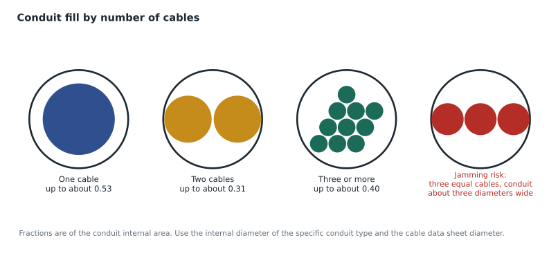
The Canadian Electrical Code, in Table 8, sets the maximum fill of a conduit as a fraction of its internal cross-sectional area, depending on the number of cables or conductors: about 0.53 of the area for one cable, 0.31 for two cables, and 0.40 for three or more. The two-cable limit is the lowest because two round cables in a conduit can wedge side by side across the diameter. ANSI/TIA-569 adopts the same principle for telecommunications conduit and notes that practical capacity is often lower than the maximum, especially for long runs with bends, so many designers plan to a lower fill to leave room for growth and to keep pulling tensions down.
In words: multiply the conduit's internal area by the allowed fill fraction F, divide by the area of one cable, and round down. Use the internal area of the specific conduit type and size from the code's tables or the manufacturer's data, because internal diameters differ between EMT, rigid conduit and PVC of the same trade size. Use the cable's actual outside diameter from the manufacturer's data sheet, because category cables from different manufacturers differ, and larger category ratings and power-over-Ethernet-optimized cables are often thicker.
Fill for mixed cables and inner duct
Pathways often carry more than one cable type. When a conduit or tray carries cables of different diameters, the fill calculation simply adds up the area of each cable: the total cable area is the sum of the number of each type multiplied by its own area. The same fill fraction then applies. Inner duct is treated as a cable for the fill of the conduit that contains it, using the inner duct's outside diameter, and the cables inside each inner duct are then checked against the inner duct's own internal area. Because inner duct takes up space itself, a conduit divided into three inner ducts holds fewer cables in total than the same conduit left open, but the cables can be added and removed independently, which is often worth the loss.
Fill calculations should be documented in the pathway schedule, conduit by conduit, so that an inspector, a contractor or a future designer can check them. Daniel's schedule lists each conduit's identifier, type, trade size, internal area, the cables assigned to it, the calculated fill and the remaining capacity. When the owner later asks whether the imaging suite conduit can take four more cables, the answer is a quick look at the schedule.
Worked problem
How many cables fit in one conduit?
A horizontal conduit to a classroom on Harbourview's third floor is 27 mm (trade size 1) EMT with an internal diameter of about 26.6 mm. The specified four-pair cable has an outside diameter of 6.1 mm. How many cables may it hold at the 0.40 fill limit?
Show solution
- Conduit internal area: π/4 × 26.6² ≈ 556 mm².
- Allowed fill area: 0.40 × 556 ≈ 222 mm².
- Cable area: π/4 × 6.1² ≈ 29.2 mm².
- Maximum cables: 222 ÷ 29.2 ≈ 7.6, rounded down to 7.
- Check the jam ratio, below, if exactly three cables will be pulled; with seven it does not apply.
Answer: Seven cables at most; Roz's office standard of planning to a lower fill would allocate this conduit for five or six.
Worked problem
Choosing a conduit size for a cable count
A conduit from telecommunications room A to the clinic's imaging suite must carry 20 of the same cables. Which EMT size is the smallest that meets the 0.40 fill limit? Internal diameters are about 40.9 mm for trade size 41 and 52.5 mm for trade size 53.
Show solution
- Cable area needed: 20 × 29.2 = 584 mm².
- Conduit internal area needed at 0.40 fill: 584 ÷ 0.40 = 1,460 mm².
- Trade size 41: π/4 × 40.9² ≈ 1,314 mm², too small.
- Trade size 53: π/4 × 52.5² ≈ 2,165 mm², which is enough.
Answer: Trade size 53 EMT, which also leaves room for growth.
Jamming
A special problem arises when exactly three cables of the same size are pulled through a conduit whose internal diameter is close to three times the cable diameter. At a bend, the cables can line up side by side across the conduit and wedge, a condition called jamming. Electrical practice identifies the risky range as a ratio of conduit internal diameter to cable diameter of roughly 2.8 to 3.2. Outside that range, the cables cannot all fit across the diameter, or they have room to rearrange. When the ratio falls in the risky range, the designer should choose a different conduit size or a different number of cables.
Fill in trays, supports and raceways
Lesson 8 introduced the rules for open pathways. For cable tray, plan no more than about half the usable cross-section and a cable depth of no more than about 150 mm. For J-hooks and other non-continuous supports, load each support within the manufacturer's rated cable count for the cable diameter in use, which often means fewer cables than the hook looks able to hold. For surface raceway and furniture channels, use the manufacturer's rated capacity, which is usually based on about two fifths of the channel area. In every case the fill calculation follows the same pattern as for conduit: total cable area, divided by the allowed fraction, compared with the pathway's usable area.
Cable bend radius
Cables have bend radius limits of their own, set by the cabling standards and by manufacturers, and the pathway must respect them everywhere: in conduit bends, in pull boxes, at tray drops, inside outlet boxes and behind patch panels. Bending a cable too tightly deforms its structure, which in twisted-pair cable disturbs the pair geometry that controls crosstalk and return loss, and in optical fibre causes macrobend loss or cracks the glass.
| Cable | Typical minimum bend radius | Notes |
|---|---|---|
| Four-pair balanced twisted-pair (unshielded) | About 4 times the cable diameter, installed | Per the ANSI/TIA-568 copper standard; check the manufacturer |
| Four-pair screened or shielded | About 8 times the cable diameter, installed | Stiffer construction; check the manufacturer |
| Multipair backbone copper | About 10 times the cable diameter | Large cables need large pull boxes and drops |
| Inside plant optical fibre, small fibre counts | About 25 mm with no load and 50 mm under pulling load | Per the ANSI/TIA-568 fibre standard |
| Other optical fibre cables | About 10 times the cable diameter with no load, 20 times under pulling load | Unless the manufacturer specifies otherwise |
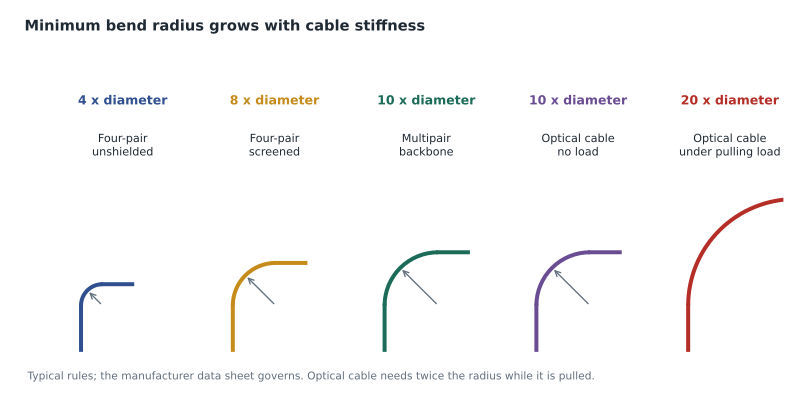
Two rules of thumb follow. First, conduit bend radius rules from lesson 7, at six or ten times the conduit's internal diameter, are generally generous enough for the cables inside, but pull boxes, outlet boxes and tray fittings are where cable bend radius is usually violated. Second, fibre needs twice the radius during pulling as at rest, so pull points and fittings on fibre routes must be sized for the pulling radius, not the installed one.
Pulling tension and pull points
Every cable also has a maximum pulling tension. For four-pair balanced twisted-pair cable, the cabling standards set a commonly cited maximum of about 110 N, which is surprisingly little; a person can easily exceed it by hand. Inside plant fibre cables with small fibre counts are commonly limited to about 220 N, and outside plant fibre cables and large backbone cables have higher limits set by the manufacturer. Exceeding the limit stretches conductors, distorts pairs or strains fibre, and the damage may not show until testing or months later.
The pathway design controls pulling tension through three choices: the length of each section, the number and radius of bends, and the friction between cable and pathway. Lesson 7's rules for conduit, 30 m and 180 degrees between pull points, are what keep typical horizontal pulls within the limits. For long backbone or entrance pulls, the cabling contractor or the cable manufacturer may calculate the expected tension using the capstan relationship from lesson 7, and the design may need extra pull points, larger conduits, lubricant or pulling from the middle of a run in both directions.
Pull points have to work in practice. A pull box must be accessible, large enough for the cable's pulling bend radius and placed in a straight section. A pull point in a ceiling must be reachable without moving ducts or removing a fixed ceiling. And a pull cord rated for the pull should be left in every empty conduit, with both ends secured and labelled, so the next installer does not have to fish a new one.
Worked problem
A fibre backbone pull
A fibre backbone cable will be pulled from the equipment room up the stack of telecommunications room A to the fourth floor, then 45 m horizontally through conduit to the college's server cupboard. The horizontal conduit has three 90-degree bends. The cable's manufacturer gives a minimum bend radius of 20 times the cable diameter under load and a cable diameter of 12 mm. What should Daniel check?
Show solution
- Pull point spacing: 45 m with 270 degrees of bends needs at least one pull box, placed so each section has no more than 30 m and 180 degrees.
- Pull box size: the cable must pass through without bending tighter than 20 × 12 = 240 mm under load, so the box must be large enough for that radius; a small electrical junction box will not do.
- Conduit bends: they must have an inside radius of at least 10 times the conduit's internal diameter because the conduit carries fibre.
- Tension: ask the contractor to confirm the expected pulling tension against the manufacturer's limit, and to use a swivel and a break-away link so the limit cannot be exceeded.
Answer: Add a correctly sized, accessible pull box in a straight section, confirm the conduit bends meet the fibre rule, and require tension control on the pull.
Common mistakes
MistakeTwo cables can fill a conduit to 0.40 like any other number.
InsteadThe limit for two cables is about 0.31, because two round cables wedge across the diameter.
MistakeFill is calculated from the trade size.
InsteadUse the internal area of the specific conduit type and size, and the cable's actual diameter from its data sheet.
MistakeIf conduit bends meet the conduit rules, cable bend radius is never a problem.
InsteadPull boxes, outlet boxes and tray fittings are where cable bend radius is usually violated.
MistakePulling tension only matters for big cables.
InsteadFour-pair cable has a low limit, about 110 N, which is easy to exceed by hand.
Summary and key terms
- The CEC (Table 8) limits conduit fill to about 0.53 of the internal area for one cable, 0.31 for two and 0.40 for three or more.
- Calculate fill from the conduit's internal area and the cable's actual diameter, and round down; many designers plan below the maximum.
- Avoid conduit-to-cable diameter ratios of about 2.8 to 3.2 when pulling three cables, to prevent jamming.
- Trays: about half the usable area and up to about 150 mm of depth; supports and raceways: manufacturer ratings.
- Respect cable bend radius everywhere, especially at pull boxes, outlet boxes and tray fittings; fibre needs twice the radius under load.
- Keep pulling tension below cable limits, about 110 N for four-pair cable, by limiting section length and bends and providing usable pull points.
- Fill fraction
- The share of a pathway's internal area that cable may occupy.
- Internal area
- The cross-sectional area inside a conduit, based on its internal diameter.
- Jamming
- Wedging of three equal cables across a conduit at a bend.
- Jam ratio
- The ratio of conduit internal diameter to cable diameter.
- Bend radius
- The minimum radius to which a cable can be bent without damage.
- Pulling tension
- The force applied to a cable while it is pulled into a pathway.
Practice problems
Work each problem on paper first, then reveal the answer to check.
Why must fill be calculated with the cable's actual diameter?
Show answer
Diameters vary by manufacturer and category, and larger modern cables can reduce capacity sharply.
Why are pull boxes for fibre larger than for copper of the same count?
Show answer
Fibre needs a larger bend radius under pulling load, and the box must accommodate it.
When does the jam ratio matter?
Show answer
When exactly three cables of the same size are pulled through a conduit about three cable diameters wide.
Lesson quiz · 5 questions
Score 60% or more to complete this lesson.
Create a free account to save your progress, take quizzes and earn a certificate.