
RCDD-111 · Lesson 1 of 12 · 20 min
The ICT infrastructure hierarchy
▶ Video coming soon A video version of this lesson is on the way.
Daniel Oyelaran has pulled thousands of cables through other people's designs. For five years he worked for a cabling contractor, terminating jacks, dressing patch panels and fighting with conduits that had too many bends and telecommunications rooms that were really broom closets with a backboard. Now he sits on the other side of the table. Lakehead Signal Design Group in Thunder Bay has hired him as a junior designer, and his mentor, Rosalind Achterberg, RCDD, has handed him the floor plans for the Harbourview Health & Learning Centre: a four-storey building with clinic floors, college classrooms and offices, a small data room, and a campus link to an existing building 400 m away. 'Before you draw a single cable,' Roz tells him, 'draw the rooms and the routes. Cabling lasts fifteen or twenty years. Spaces and pathways last as long as the building. Get them wrong and every cable you ever install will pay for it.'
This course is about those rooms and routes, the part of information and communications technology (ICT) design that the RCDD exam treats as the foundation for everything else. It follows the design of Harbourview from the outside in: how services enter the building, where equipment lives, how many telecommunications rooms the floors need and how big they must be, what environment and power those rooms require, and how conduit, cable tray, raceway, ceilings and floors carry cable between them. It ends with firestopping, where pathways cross fire separations, and with the coordination that keeps the ICT design from colliding with structure, mechanical systems and electrical work. This first lesson builds the map that every later lesson uses: the hierarchy of spaces and cabling subsystems that the standards describe.
A note on independence: HSM University is not affiliated with or endorsed by BICSI. RCDD is a registered credential of BICSI. This course is an independent study aid. It explains published principles in its own words and cites standards by number; it does not reproduce the text, tables or figures of the BICSI Telecommunications Distribution Methods Manual or of any standard. The quiz and exam questions are original practice items, not real exam questions.
Why a hierarchy at all
Early telephone wiring in buildings grew without a plan. Each new line was run from wherever the phone company's equipment happened to be to wherever the new phone happened to be. By the 1980s, as computer networks arrived beside telephones, buildings were full of abandoned cable, unlabelled pairs and proprietary wiring that worked with only one vendor's equipment. The structured cabling standards that followed, beginning with the first TIA/EIA-568 standard in 1991 and the Canadian CSA T529 that paralleled it, replaced that chaos with a simple idea: cabling should be designed as a generic, vendor-neutral system organized into a small number of subsystems, each connecting at defined spaces, so that any application can run on it and any part can be changed without disturbing the rest.
The hierarchy is what makes that possible. If every work area outlet connects back to a cross-connect in a known room, and every room connects to a central room through a predictable backbone, then adding a floor, replacing switches or moving a department becomes routine patching rather than new construction. The hierarchy also makes design repeatable: once you know the rules for one telecommunications room and the horizontal cabling it serves, you can apply them to every floor of every building.
The spaces, from the street to the desk
The current family of cabling standards, ANSI/TIA-568 and ANSI/TIA-569 together with their Canadian adoptions and the related CSA T530 guidance on building facilities, describes a set of spaces. You will meet each of them in detail later in the course, but it helps to see them all at once.
- Entrance facility (EF): the point where outside cables, from service providers or from other campus buildings, enter the building and are protected, terminated and handed over. It may be a room, a wall in a shared room or a small cabinet.
- Equipment room (ER): a centralized, environmentally controlled space for telecommunications equipment that serves the whole building or campus, such as core switches, servers, telephone systems and the main cross-connect.
- Telecommunications room (TR): a room on each floor that houses the horizontal cross-connect, the switches that serve that floor and the termination of horizontal cabling.
- Telecommunications enclosure (TE): a cabinet or enclosure that can serve a small area in place of a full room, for example a few offices or a reception area.
- Work area (WA): the space where occupants use telecommunications equipment, from a desk to a nurses' station or a classroom lectern, served by telecommunications outlets.
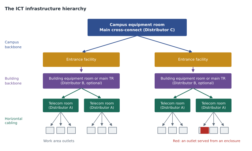
Larger campuses add a further layer. The building where the campus backbone starts usually holds the main equipment room, and each other building has its own entrance facility, equipment room or main telecommunications room. Data centres have their own spaces and vocabulary, which RCDD-115 covers.
Cabling subsystems and distributors
The same hierarchy can be described by the cabling rather than the rooms. The current TIA-568 framework names three cabling subsystems connected by distributors. Cabling Subsystem 1 runs from the work area outlet to the first distributor, Distributor A, which is normally in the telecommunications room; this is what most people call horizontal cabling. Cabling Subsystem 2 connects Distributor A to Distributor B, and Cabling Subsystem 3 connects Distributor B to Distributor C, the top of the hierarchy. Subsystems 2 and 3 together are the backbone.
Older and more familiar names are still everywhere on drawings and in conversation, and the exam expects you to translate between them. Distributor C corresponds to the main cross-connect (MC), Distributor B to an intermediate cross-connect (IC), and Distributor A to the horizontal cross-connect (HC). The international standard, ISO/IEC 11801, uses yet another set: campus distributor (CD), building distributor (BD) and floor distributor (FD), with the telecommunications outlet (TO) at the work area.
| Role | TIA generic name | Traditional TIA name | ISO/IEC 11801 name | Usual location |
|---|---|---|---|---|
| Top of the hierarchy | Distributor C | Main cross-connect (MC) | Campus distributor (CD) | Main equipment room |
| Middle level (optional) | Distributor B | Intermediate cross-connect (IC) | Building distributor (BD) | Building equipment room or main TR |
| Serves a floor or area | Distributor A | Horizontal cross-connect (HC) | Floor distributor (FD) | Telecommunications room or enclosure |
| End of the horizontal | Equipment outlet | Telecommunications outlet | Telecommunications outlet (TO) | Work area |
Two rules keep the hierarchy simple. First, the backbone is a hierarchical star: each horizontal cross-connect connects to the main cross-connect either directly or through one intermediate cross-connect, and never through more than two levels of backbone cross-connect. Second, the horizontal is also a star: each outlet is cabled directly to its distributor, without bridges, splits or daisy chains. A single optional consolidation point or multi-user outlet is allowed in open-plan areas, a topic covered in RCDD-112, but the principle remains one cable, one outlet, one distributor.
Distance shapes the spaces
The reason telecommunications rooms exist on every floor, and the reason their locations matter so much, comes down to distance. Balanced twisted-pair horizontal cabling is limited to 90 m of permanent link from the distributor to the outlet, with up to 10 m more allowed for patch cords and equipment cords, giving a channel of 100 m. Those figures are measured along the actual cable route, not on the floor plan as the crow flies. Cable rises out of the rack, travels along ladder rack and up to the ceiling, follows corridors and drops down walls, so a desk that looks 70 m away on the plan can easily be at the limit.
Backbone distances are longer and depend on the medium and application, and they are covered in RCDD-112. The spaces and pathways designer's job is to place rooms so that every outlet is within reach of its distributor along a realistic route, to place the rooms so they stack vertically for short backbone runs, and to provide pathways big enough for today's cable and tomorrow's.
Worked problem
Checking a route against the horizontal limit
On the third floor of Harbourview, the planned telecommunications room sits near the central core. The farthest classroom outlet is 48 m east and 22 m north of the room on the plan. Daniel estimates the cable route as follows: 3 m up and over the ladder rack inside the room, the corridor route east then north in the ceiling, plus an allowance of 10 m for detours around ducts, and 4 m down the classroom wall to the outlet. Is the outlet within the permanent link limit?
Show solution
- Corridor route: cable does not cut diagonally across rooms, so use the two legs, 48 + 22 = 70 m.
- Add the vertical and allowance pieces: 70 + 3 + 10 + 4 = 87 m.
- Compare with the limit of 90 m. The estimate is inside the limit, but only by 3 m.
- A margin that small leaves no room for a route change during construction or for slack loops. Daniel flags the classroom so that the room location, or a second telecommunications room on the floor, can be checked in lesson 5.
Answer: Yes, about 87 m against a limit of 90 m, but with too little margin to be comfortable.
Spaces and pathways as long-life infrastructure
Roz's point about lifespan is one of the most important ideas in this field. Active equipment, such as switches and wireless access points, is typically replaced every five to seven years. Cabling is commonly designed for fifteen to twenty years and may last longer. The building and its rooms, sleeves, conduits and shafts are expected to last for decades. A designer who saves a little money by shrinking a telecommunications room or omitting spare conduit imposes a cost on every future tenant and every future technology refresh. Retrofitting a sleeve through a concrete slab, or finding space for a new room in an occupied building, costs far more than providing them during construction.
That is why the standards push designers to plan spaces and pathways for the building's whole life and to include growth: spare sleeves, room for additional racks, larger conduits than today's cable count requires, and pathways that can be reached without demolition. It is also why spaces and pathways are among the first things to coordinate with the architect. Once walls, shafts and structure are fixed, the ICT designer has to live with them.
The codes and standards behind this course
Spaces and pathways sit at the meeting point of voluntary standards and mandatory codes, and the RCDD candidate needs to keep the two straight. The design standards are consensus documents such as ANSI/TIA-569 (telecommunications pathways and spaces), ANSI/TIA-568 (cabling), ANSI/TIA-606 (administration), ANSI/TIA-607 (bonding and grounding) and ANSI/TIA-758 (outside plant), together with ISO/IEC 11801 and related international documents. In Canada, CSA publishes Canadian versions and companion guidance, such as CSA T530 for building facilities, which designers often apply alongside the TIA documents. Standards become binding when a contract or specification calls them up.
Codes are different: they are law where they have been adopted. In Canada, the Canadian Electrical Code, Part I, sets safety rules for communications circuits in Section 60, and the National Building Code of Canada, as adopted by each province, governs fire separations and the firestopping of penetrations. Where a standard and a code disagree, the code governs, and the authority having jurisdiction (AHJ) has the final word on how the code applies. Lesson 11 returns to the AHJ in the context of firestopping.
| Topic | Main design standard | Mandatory code that also applies |
|---|---|---|
| Spaces and pathways | ANSI/TIA-569 | National Building Code of Canada (as adopted); CEC Section 60 |
| Cabling | ANSI/TIA-568 series; ISO/IEC 11801 | CEC Section 60 (listing and installation of cables) |
| Administration and labelling | ANSI/TIA-606 | Usually none; called up by specification |
| Bonding and grounding | ANSI/TIA-607 | CEC Sections 10 and 60 |
| Outside plant | ANSI/TIA-758 | CEC Section 60; provincial and municipal rules |
Who does what on a project
An ICT designer rarely works alone. On Harbourview, the architect owns the floor plans and the location of rooms and shafts; the electrical engineer, Priya Raman, owns power, lighting and the electrical code; the mechanical engineer owns cooling, ventilation and sprinklers; and the structural engineer decides where slabs can be cored. The general contractor's project manager, Marcus Feld, will schedule the trades, and the cabling contractor's foreman, Tomasz Wiercinski, will install what Daniel draws. The RCDD's job is to know enough about each discipline to ask for the right things early: a room in the right place with the right size, a shaft that lines up from floor to floor, power and cooling that match the equipment, and penetrations that can be firestopped with a listed system.
Roz keeps a short list pinned above her desk, which she calls the three questions: where does the cable come from, where does it go, and what does it pass through on the way? Every space and pathway decision in this course answers one of them.
Common mistakes
MistakeThe telecommunications room can go wherever there is leftover space.
InsteadRoom location is driven by cable distance and vertical alignment, and it must be agreed with the architect early.
MistakeHorizontal distance can be measured on the floor plan in a straight line.
InsteadMeasure along the real route, including vertical runs, detours and slack, and keep a margin.
MistakeA building needs only one backbone cross-connect level, so intermediate cross-connects are wrong.
InsteadOne intermediate level is allowed; what the standards forbid is more than two levels of backbone cross-connect.
MistakeIf a standard says it, it is the law.
InsteadStandards become binding through contracts; codes are law where adopted, and the AHJ interprets them.
Summary and key terms
- Structured cabling organizes spaces and cabling into a vendor-neutral hierarchy so any application can run and any part can be changed.
- The spaces are the entrance facility, equipment room, telecommunications rooms and enclosures, and work areas.
- Backbone cabling forms a hierarchical star with no more than two levels of backbone cross-connect; horizontal cabling is a star from each outlet to its distributor.
- Distributor A, B and C correspond to the horizontal, intermediate and main cross-connects, and to the floor, building and campus distributors in ISO/IEC 11801.
- The horizontal permanent link is limited to 90 m and the channel to 100 m, measured along the real cable route.
- Spaces and pathways outlast cabling and equipment, so they should be designed with growth for the life of the building.
- Standards guide design; codes are law where adopted, and the authority having jurisdiction interprets them.
- Entrance facility
- The space where outside cables enter a building and are protected and terminated.
- Equipment room
- A centralized, controlled space for equipment serving a building or campus.
- Telecommunications room
- A floor-serving space for the horizontal cross-connect and related equipment.
- Telecommunications enclosure
- A cabinet that serves a small area in place of a full room.
- Distributor
- A point where cabling subsystems are connected, such as a cross-connect.
- Hierarchical star
- A topology in which each level connects to the level above it through a single path.
- Authority having jurisdiction
- The official or body responsible for enforcing a code and approving installations.
Practice problems
Work each problem on paper first, then reveal the answer to check.
Why does the hierarchy forbid more than two levels of backbone cross-connect?
Show answer
Each additional level adds connections, loss, complexity and points of failure; two levels are enough to reach any floor of a large campus.
A drawing labels a room 'FD-3'. What does that most likely mean?
Show answer
Floor distributor 3, the ISO/IEC 11801 name for a horizontal cross-connect serving the third floor or an area of it.
Why should spaces and pathways be designed with more growth than the cabling?
Show answer
They last for the life of the building and are very expensive to add later, while cabling and equipment are replaced several times.
Lesson quiz · 5 questions
Score 60% or more to complete this lesson.
Create a free account to save your progress, take quizzes and earn a certificate.