
RCDD-111 · Lesson 5 of 12 · 18 min
Sizing and locating spaces
▶ Video coming soon A video version of this lesson is on the way.
The architect has sent a polite but firm email. The clinic operator wants as much floor area as possible for exam rooms, and the architect asks whether the two telecommunications rooms on each Harbourview floor could become one, and whether that one room could be 2 m by 2.5 m instead of the size Daniel requested. Roz forwards it to Daniel with a one-line note: 'Show them the numbers.' This lesson is about the numbers: how many telecommunications rooms a floor needs, where they should go, and how large they must be, with the reasoning laid out so clearly that an architect, an owner or an exam question can follow it.
Sizing is where the ICT designer most often has to defend space against other demands. Every square metre given to a telecommunications room is taken from rentable area, exam rooms or classrooms, so owners and architects push back. The best defence is a calculation that starts from the floor area served and the cable distance limit, checks the result against the equipment that must fit, and shows the growth allowance explicitly. An undersized room is not a saving; it is a cost deferred to the first technology refresh, when there is no space for new equipment beside the old.
How many rooms does a floor need?
Two tests decide whether one telecommunications room is enough for a floor. The first is area. ANSI/TIA-569 guidance calls for additional rooms when the usable floor area served by one room exceeds about 1,000 m². The second is distance. Every outlet must be reachable within the 90 m permanent link limit along the real cable route, including vertical runs inside the room, routing around obstacles and slack. On large or long floors, the distance test usually decides the matter before the area test does, because cable routes follow corridors rather than straight lines.
A third consideration is the building's shape. An L-shaped or U-shaped building, or a floor divided by a fire wall or an atrium, may need a room in each wing even when the total area is small, because routes between wings are long or difficult. Tenancy matters too: if a floor will be leased to several tenants, each with its own space, the designer may want rooms placed so that each tenant is served without cables crossing another tenant's area.
In words: divide the usable area by the area one room may serve and round up, then check every outlet's route distance. If any route is too long, add a room or move one. The number of rooms is the larger of the two answers.
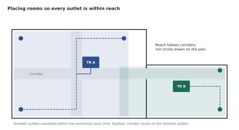
Placing the rooms
Once the number is known, location follows a few principles. A room should be as close as practicable to the centre of the area it serves, so that the longest routes are as short as possible and the room can grow its area of service in every direction. It should be next to, or easy to reach from, the backbone pathway, which usually means near the building core and stacked above and below with the rooms on other floors, as lesson 4 explained. It should be accessible from a corridor or common area, not through an office or a tenant space. And it should avoid the same hazards as an equipment room: water, strong electromagnetic interference, exterior walls and spaces that other trades use.
Building cores are crowded. Stairs, elevators, washrooms, electrical rooms, mechanical shafts and janitor closets all compete for the same few positions, and the telecommunications room often loses. Placing the room beside the electrical room is common, because both need vertical shafts and both are serviced by trades rather than occupants, but the rooms must be separate, and the telecommunications room should not share a wall with large transformers. Placing it beside a washroom is common too, but then no plumbing may run through or over it.
How big should each room be?
Once again there are two methods, and the designer should use both. The first is a planning guideline based on the area served. Editions of ANSI/TIA-569 have expressed this in different ways over the years; the long-familiar guidance was a room of about 3 m by 3.4 m for a room serving the full 1,000 m², with somewhat smaller rooms allowed for smaller areas. More recent practice also sizes rooms from the number of racks and the clear space they need. Because the guidance changes between editions, the designer checks the edition called up by the project rather than quoting a number from memory.
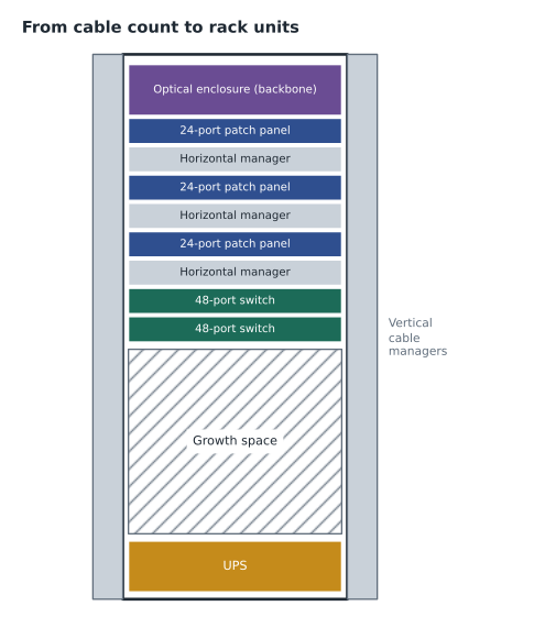
The second method works from what the room must hold. Start with the number of horizontal cables the room will terminate, including every outlet type, then convert to patch panel ports, rack units and racks, and add the active equipment, the backbone terminations, building systems equipment and growth. Then lay out the racks with clear space in front and behind, add the wall space for the backboard and wall-mounted equipment, and draw the room around the result.
| Step | What to count | Typical assumptions to confirm |
|---|---|---|
| 1. Work areas | Usable area divided by area per work area, or a count from the furniture plan | About one work area per 10 m² in general offices; specific counts for clinics, classrooms and labs |
| 2. Horizontal cables | Cables per work area plus wireless access points, cameras, phones, building systems and spares | Often two or more cables per work area, plus device counts from other disciplines |
| 3. Patch panel space | Cables divided by ports per panel, plus cable managers | For example 24- or 48-port panels with a horizontal manager per panel or pair of panels |
| 4. Active equipment | Switches, uplinks, UPS, building system panels | Switch port counts matched to the cable count, with power over Ethernet budgets |
| 5. Racks | Total rack units divided by usable units per rack, rounded up, plus growth racks | Usable units per rack and the growth allowance set by the owner |
| 6. Room | Rack row, aisles, backboard wall and door swing | Clearances from the standard, the electrical code and the equipment |
Rooms for special occupancies
General office densities do not fit every building. Healthcare floors like Harbourview's clinics have exam rooms, nurse stations, medication rooms and imaging suites, each with its own outlet count, and often more wireless access points, nurse call devices and real-time location sensors than an office of the same size. Classrooms need outlets for lecterns, displays, cameras and wireless coverage dense enough for every student to carry two or three devices. Laboratories and workshops need outlets at benches and equipment. In each case the designer should replace the general planning density with a count from the occupant's room data or furniture plans as early as possible, because the cable count, and therefore the size of every telecommunications room, follows from it.
Device counts from other disciplines are easy to miss. Building automation sensors, access control readers, cameras, digital signage, emergency phones and distributed antenna system remote units may all be cabled to the telecommunications rooms. The designer should ask each discipline for its device list during design development and add it to the room calculation, rather than discovering the devices when their installers arrive.
Recording the basis of design
Every sizing decision should be written into a short basis-of-design statement: the floor areas served, the planning densities and device counts used, the cable and rack calculations, the growth allowance and the source of each assumption. Owners change, staff change and designs are revised, and a written basis lets anyone check later whether the rooms are still adequate. On Harbourview, Daniel's basis-of-design statement becomes an appendix to the design report, and when the college later asks to add a lecture-capture system, the effect on room B can be checked in minutes instead of being argued from memory.
Worked problem
Checking the clinic floor rooms
The second floor of Harbourview is a clinic of about 1,500 m² usable area. The furniture plan shows 60 work areas (exam rooms, nurse stations and offices) needing two cables each, plus 14 wireless access points, 10 cameras, 12 building system devices and 10 spare cables. The floor has two telecommunications rooms. How many rack units of patch panels and managers does each room need, and does one room per floor satisfy the area test?
Show solution
- Area test: 1,500 ÷ 1,000 = 1.5, which rounds up to 2 rooms. One room would not satisfy the guideline, and the long routes into the east wing point the same way.
- Total cables: 60 × 2 + 14 + 10 + 12 + 10 = 166 cables, split roughly in half between the two rooms, 83 cables each.
- Patch panels: 83 ÷ 24 = 3.46, so 4 panels of 24 ports per room, with 13 ports to spare.
- Managers: one 1U horizontal manager per panel gives 4U of managers, so panels and managers need 4 + 4 = 8 rack units.
- Add backbone fibre (2U), two 48-port switches with managers (4U), a small UPS (2U) and an equal amount of growth space: about (8 + 2 + 4 + 2) × 2 = 32 rack units, which fits one rack, so each room needs space for one rack plus a second growth rack.
Answer: About 16 rack units of equipment per room today, 32 with growth: one rack now and a second for growth, in each of two rooms. One room per floor fails the area test.
Answering the architect
Daniel writes back to the architect with three points. First, the floor area served exceeds the guideline for one room, so two rooms are needed; merging them would also push the farthest exam rooms beyond the cable distance limit. Second, each room must hold two racks with clear aisles, a backboard wall and an outward door, which needs a room of about 3 m by 3.4 m; the proposed 2 m by 2.5 m room cannot fit one rack with legal clearances. Third, he offers a compromise that costs the clinic nothing: the second-floor rooms can be rotated to sit against a shaft wall the clinic cannot use for exam rooms anyway. The architect accepts the rotation and the size.
This is the pattern for most space negotiations. Show the calculation, show the equipment, show the growth, and look for a location that costs the owner less without making the cabling worse.
Other spaces to size
The same two-method approach applies to entrance facilities and equipment rooms. Entrance facilities are sized from the number of providers and campus cables, the space each provider requires for its terminations and equipment, and the protectors and splice cases, with the backboard length growing with the size of the building. Equipment rooms are sized with the planning ratio from lesson 3 and checked against the equipment list. Telecommunications enclosures are sized by the vendor's enclosure dimensions and the equipment they hold, but they also need clear space in front for a technician to work and to open the door fully.
Some buildings need spaces the basic hierarchy does not name: a room for a distributed antenna system head-end, a security operations room, an audiovisual equipment room for a lecture theatre, or a small data room within the equipment room. Each should be listed and sized early, because the architect's first plan will not include them, and later requests for space are always harder to win.
Common mistakes
MistakeIf the area served is below the guideline, one room is always enough.
InsteadThe distance test can require more rooms even on a small floor, especially on long or L-shaped floors.
MistakeDistance can be checked with a compass on the floor plan.
InsteadReach zones follow corridors and real routes, including vertical runs and slack.
MistakeSize the room from today's outlet count.
InsteadCount every cable type, add active equipment and building systems, and include an explicit growth allowance.
MistakeArguing for space means refusing every change.
InsteadShow the calculation, then look for locations that cost the owner less without harming the design.
Summary and key terms
- Add telecommunications rooms when the usable area served by one room exceeds about 1,000 m² or when any route exceeds the 90 m permanent link limit.
- Building shape, fire walls, atriums and tenancy can require more rooms than the area test alone suggests.
- Place rooms near the centre of the area served, next to the backbone, stacked, accessible from common areas and away from water and EMI.
- Size rooms with the planning guideline in the current edition and check with a bottom-up count of cables, panels, equipment, racks and clearances.
- Write down every assumption so the architect and owner can check the result.
- Apply the same approach to entrance facilities, equipment rooms, enclosures and special-purpose rooms.
- Area served
- The usable floor area whose outlets are cabled to a given room.
- Reach zone
- The part of a floor whose outlets can be reached within the horizontal route limit.
- Rack unit
- A standard height of 44.45 mm (1.75 in) used to measure equipment in racks.
- Work area density
- The number of work areas per unit of floor area.
- Growth allowance
- Space and capacity reserved for future equipment and cable.
- Bottom-up sizing
- Sizing a space from the equipment and cables it must hold.
Practice problems
Work each problem on paper first, then reveal the answer to check.
Why can a small L-shaped floor need two telecommunications rooms?
Show answer
Routes between the wings may exceed the distance limit even though the total area is small.
Why should growth be shown explicitly in a room size calculation?
Show answer
So the owner and architect can see that the space is reserved deliberately and do not cut it as waste.
What two things should you check before agreeing to move a room?
Show answer
That every route is still within the distance limit and that the room still stacks with the rooms above and below.
Lesson quiz · 5 questions
Score 60% or more to complete this lesson.
Create a free account to save your progress, take quizzes and earn a certificate.