
PWR-320 · Lesson 8 of 12 · 24 min
Gas turbines and the Brayton cycle
▶ Video coming soon A video version of this lesson is on the way.
Keswold's steam comes from the heat of a gas turbine's exhaust, and during the outage the gas turbine had its own inspection. On Wednesday, October 7, 2026, Okonkwo stood beside the gas turbine's enclosure while the manufacturer's field engineer fed a flexible borescope through an inspection port into the compressor and, later, through the igniter openings into the combustors. The images appeared on a screen on a trolley: compressor blades with dulled leading edges and a faint film of dirt, the inside of a combustion liner, the first-stage turbine nozzles with their ceramic coating.
Anselm had explained the arrangement on the first visit. The gas turbine makes about 45 MW at standard conditions; its exhaust, still at well over 500 °C, flows through the heat recovery steam generator, which raises the steam for the 18 MW steam turbine and for Marrowby Foods. "The steam turbine runs on what the gas turbine throws away," he said. "Which is why you need to understand the gas turbine first."
This lesson explains how a gas turbine works, analyses the ideal and actual Brayton cycle, shows why gas turbine output and efficiency depend so strongly on air temperature and pressure ratio, describes the variations of the cycle and the main components and support systems, and outlines how gas turbines are started, protected, stopped and washed.
Where gas turbines are used
A gas turbine compresses air, burns fuel in it at constant pressure, and expands the hot gas through a turbine that drives both the compressor and an external load. The same machine, in different forms, propels aircraft, drives pipeline compressors and pumps, powers ships, generates electricity in simple cycle peaking plants and, with a heat recovery boiler behind it, in combined cycle and cogeneration plants.
Compared with a steam plant of the same output, a gas turbine is compact and light, starts in minutes rather than hours, needs little or no cooling water, and is relatively quick to install. Its weaknesses are that a simple cycle gas turbine is less efficient than a large steam plant, because so much heat leaves in its exhaust; that it needs clean gaseous or light liquid fuels; that its output falls on hot days; and that its hot parts have a limited life and need regular inspection and replacement.
The Brayton cycle
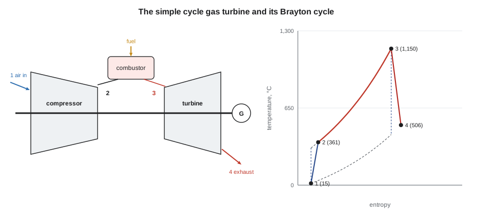
The ideal cycle of a gas turbine is the Brayton cycle, also called the Joule cycle. In its open form, air is drawn from the atmosphere and the exhaust returned to it; the ideal cycle treats the air as a perfect gas passing through four processes:
- 1 to 2, compressor: isentropic compression from atmospheric pressure to the pressure ratio r_p.
- 2 to 3, combustor: heat added at constant pressure, raising the gas to the turbine inlet temperature.
- 3 to 4, turbine: isentropic expansion back to atmospheric pressure.
- 4 to 1, exhaust: heat rejected at constant pressure, in the open cycle by discharging the exhaust and drawing in fresh air.
With constant specific heats, the isentropic temperature ratio for both compression and expansion is the same, and PWR-310's isentropic relation gives it from the pressure ratio. The ideal efficiency depends only on that ratio:
For air, γ = 1.4, so (γ − 1) ÷ γ = 0.2857. A pressure ratio of 12 gives a temperature ratio of 12^0.2857 = 2.034 and an ideal efficiency of 1 − 1 ÷ 2.034 = 0.508.
The real cycle
Real compressors and turbines are not isentropic. Their isentropic efficiencies are defined the same way as a steam turbine's (PWR-310): for the compressor, the ideal temperature rise divided by the actual; for the turbine, the actual temperature drop divided by the ideal. The crucial feature of the gas turbine is that its compressor absorbs a large share of the turbine's work, the back work ratio, typically around half. Small losses in either machine therefore make a large difference to the net output.
Worked problem
A gas turbine like Keswold's
A gas turbine has a pressure ratio of 12. Air enters at 15 °C (288.15 K) and the turbine inlet temperature is 1,150 °C (1,423.15 K). The compressor's isentropic efficiency is 0.86 and the turbine's 0.89. Take c_p = 1.005 kJ/kg·K and γ = 1.4 throughout, and ignore the fuel's mass and pressure losses. Find the compressor and turbine work, the net work, the back work ratio, the thermal efficiency, the exhaust temperature and the air flow for 45 MW.
Show solution
- Isentropic temperatures:
- \[T_{2s} = 288.15 \times 2.034 = 586.1 \text{ K} \qquad T_{4s} = \frac{1{,}423.15}{2.034} = 699.7 \text{ K}\]
- Actual compressor outlet and turbine exhaust:
- \[T_2 = 288.15 + \frac{586.1 - 288.15}{0.86} = 634.6 \text{ K} \ (361.4\ ^\circ\text{C}) \qquad T_4 = 1{,}423.15 - 0.89 \times (1{,}423.15 - 699.7) = 779.3 \text{ K} \ (506.1\ ^\circ\text{C})\]
- Compressor and turbine work:
- \[w_c = 1.005 \times (634.6 - 288.15) = 348.2 \text{ kJ/kg} \qquad w_t = 1.005 \times (1{,}423.15 - 779.3) = 647.1 \text{ kJ/kg}\]
- Net work and back work ratio:
- \[w_{net} = 647.1 - 348.2 = 298.9 \text{ kJ/kg} \qquad \text{BWR} = \frac{348.2}{647.1} = 0.538\]
- Heat added and efficiency:
- \[q_{in} = 1.005 \times (1{,}423.15 - 634.6) = 792.5 \text{ kJ/kg} \qquad \eta = \frac{298.9}{792.5} = 0.377\]
- Air flow for 45 MW:
- \[\dot m = \frac{45{,}000}{298.9} = 150.5 \text{ kg/s}\]
Answer: The compressor uses 54 in 100 of the turbine's work, so only 46 in 100 is left to drive the generator. The efficiency of 0.377 is far below the ideal 0.508 for the same pressure ratio. A real machine does worse again, because some compressed air bypasses the combustor to cool the turbine blades, the inlet, combustor and exhaust all lose pressure, and the gas's specific heat changes with temperature: Keswold's gas turbine reaches about 0.34 and exhausts at about 545 °C at full load.
Gas turbine efficiency is often quoted as a heat rate, the fuel energy per kilowatt-hour, usually on the fuel's lower heating value. An efficiency of 0.34 corresponds to 3,600 ÷ 0.34 = 10,590 kJ/kWh. The two things that most raise efficiency and output are a higher turbine inlet temperature and an appropriately higher pressure ratio. Inlet temperatures in modern heavy-duty machines are far above the melting point of the blade alloys, made possible by internal air cooling of the blades and vanes, ceramic thermal barrier coatings and single-crystal superalloy castings.
Ambient conditions
A gas turbine is a constant-volume machine: at a given speed, its compressor draws a nearly constant volume of air. On a hot day the air is less dense, so the mass flow falls, and the compressor needs more work per kilogram because its temperature rise is proportional to the inlet temperature. Both effects reduce the output.
Worked problem
The same machine on a hot afternoon
Repeat the compressor work for an inlet temperature of 30 °C (303.15 K), keeping everything else the same. Then estimate the fall in output, allowing for the lower air density at the same volume flow.
Show solution
- Compressor work at 30 °C:
- \[w_c = 1.005 \times \frac{303.15 \times (2.034 - 1)}{0.86} = 366.3 \text{ kJ/kg}\]
- Net work:
- \[w_{net} = 647.1 - 366.3 = 280.8 \text{ kJ/kg} \quad (0.939 \text{ of the 15 °C value})\]
- Mass flow ratio at the same volume flow:
- \[\frac{288.15}{303.15} = 0.951\]
- Output ratio:
- \[0.939 \times 0.951 = 0.893\]
Answer: The simple estimate gives a loss of about a tenth of the output for a hot afternoon, and Keswold sees about the same: around 40 MW in summer heat against 45 MW at standard conditions. The rating conditions used for gas turbines, 15 °C (59 °F), sea level pressure and 60 in 100 relative humidity, are the **ISO conditions**, and nameplate ratings are always stated at them.
Plants recover some of the lost output by inlet air cooling: evaporative coolers or foggers, which cool the air by evaporating water into it and work best in dry weather, or chillers. Keswold has an evaporative cooler in its inlet house, used in summer. In winter the opposite problem appears: the inlet can ice up in cold, humid weather, so anti-icing heats the inlet air slightly with compressor bleed air or a heating coil.
Variations on the cycle
Several modifications change the cycle's efficiency and output, and the examinations expect them to be explained:
- Regeneration: a heat exchanger, the regenerator or recuperator, uses the hot exhaust to preheat the compressed air before the combustor, so less fuel is needed. It pays only when the exhaust is hotter than the compressor discharge, which is true at low pressure ratios. It is used on some small industrial and marine machines, not where the exhaust heat goes to a HRSG.
- Intercooling: cooling the air between compressor stages reduces the compression work, raising net work. On its own it lowers efficiency slightly, because more fuel is needed, unless combined with regeneration.
- Reheat: burning more fuel between turbine stages raises net work. Like intercooling, it raises the exhaust temperature and suits combined cycles.
- Closed cycles circulate a working gas, such as helium or air, round a closed loop with heat exchangers instead of a combustor and exhaust. They allow any heat source and a pressurized working fluid, and appear in some nuclear and research designs.
- Two-shaft or free power turbine arrangements put the compressor and its driving turbine, the gas generator, on one shaft and a separate power turbine on another. The power turbine can run at the speed its load needs, which suits compressors and pumps; aeroderivative gas turbines for power generation often use this arrangement.
- Steam injection or water injection into the combustor raises output by adding mass flow and reduces nitrogen oxide formation, at some cost in efficiency and water use.
The components
Compressors on large gas turbines are axial, with many stages of moving and stationary blades and the air speeding up and slowing down in each. A compressor stalls and surges, with violent flow reversal, if it is asked for too much pressure ratio at too low a flow, especially during starting and stopping. Gas turbines prevent it with variable inlet guide vanes (IGVs), which turn to reduce the air flow at low speed and low load, and with bleed valves that release air from intermediate stages during starting. The IGVs are also used to hold the exhaust temperature up at part load in combined cycle plants, which keeps the HRSG productive.
Combustors may be a ring of separate cans (can-annular), a single annular chamber, or one or two large silos. Most new natural gas combustors are dry low NOx (DLN) or lean premix designs, which mix fuel and air thoroughly before burning so that the flame temperature stays below the level at which nitrogen oxides form rapidly. They need careful tuning of the fuel split between several fuel circuits, and can suffer combustion dynamics, pressure pulsations in the combustor that can crack parts if not controlled. Keswold's gas turbine has ten DLN combustion cans, with flame detectors in two of them and crossfire tubes that carry the flame from can to can at light-off.
Turbines on heavy-duty machines have three or four stages. The first-stage nozzles and blades are the most highly stressed parts of the whole machine, cooled by air flowing through internal passages and out through rows of small holes over their surfaces. Their condition sets the inspection intervals: combustion inspections, hot gas path inspections and major inspections, at intervals based on fired hours and starts, as the manufacturer defines them.
Support systems
- Inlet air system: filters, often in several stages, to keep dust, salt and insects out of the compressor; silencers; and the evaporative cooler and anti-icing equipment.
- Fuel gas system: filtering, often heating to keep the gas well above its dew point, and in many plants a gas compressor to raise pipeline gas to the pressure the combustors need; a set of stop and control valves under the turbine controller.
- Lubricating oil system, much like the steam turbine's (lesson 4), with AC and DC pumps; gas turbines often use synthetic or anti-wear oils.
- Starting system: a starting motor or diesel with a torque converter on older and smaller units, or on modern generator drives a static frequency converter that runs the generator as a variable-speed motor to crank the turbine.
- Turning gear or ratchet, to keep the rotor turning slowly after shutdown while it cools.
- Enclosure ventilation, gas detection and fire protection, usually a carbon dioxide or water mist system that floods the enclosure; ventilation fans and gas detectors in the enclosure trip the unit if gas is detected.
- Exhaust system and, on a combined cycle, the HRSG and its stack, sometimes with a diverter damper or bypass stack.
The supervisory and protective system monitors speed, vibration, flame, exhaust temperature and the exhaust temperature spread, the difference between the hottest and coldest of a ring of thermocouples around the exhaust. A large or growing spread points to a combustor fault or a blocked fuel nozzle, because each can's hot streak lands at a predictable place in the exhaust.
Starting, stopping and washing
A gas turbine start follows an automatic sequence. The starting system cranks the rotor to purge speed, and the unit runs there long enough to sweep several volumes of air through the combustors, exhaust and HRSG, removing any fuel that may have collected, as the burner and HRSG safety codes require. The speed is then reduced to light-off speed, the igniters fire, fuel is admitted, and flame detectors must prove flame within a few seconds or the start aborts. The starter and the turbine together accelerate the rotor until it is self-sustaining, the starter drops out, and the unit reaches full speed no load. After synchronizing, load is raised at a rate set by the HRSG as well as by the turbine.
A normal stop unloads the unit, opens the breaker, shuts off fuel and lets the rotor coast down onto turning gear, where it stays for many hours while the hot rotor cools evenly. A trip shuts off fuel at once.
Dirt on the compressor blades reduces the air flow and the compressor's efficiency, and the loss can reach several in 100 of output. Compressors are cleaned by washing: online washing sprays demineralized water into the inlet while the unit runs, slowing the build-up; offline or crank washing, with the unit cool and cranked at low speed by the starter, sprays a detergent solution and then rinse water, and recovers much more output. Keswold's field engineer recommended an offline wash before the restart, because the borescope had shown a light film on the early compressor stages; it was done on October 8. The combustor and hot gas path images showed nothing outside the manufacturer's limits, though one first-stage nozzle segment had a small area of lost coating that was recorded for the next hot gas path inspection.
Common mistakes
MistakeUsing Celsius or Fahrenheit temperatures in the isentropic relations.
InsteadUse absolute temperatures, kelvin or degrees Rankine, in T₂ ÷ T₁ = r_p^((γ−1)/γ).
MistakeForgetting that the compressor absorbs about half the turbine's work.
InsteadNet work is turbine work minus compressor work; small component losses change it greatly.
MistakeApplying the compressor efficiency the same way round as the turbine's.
InsteadCompressor: actual rise = ideal rise ÷ η. Turbine: actual drop = η × ideal drop.
MistakeExpecting regeneration to help a gas turbine with a HRSG.
InsteadRegeneration takes the exhaust heat the HRSG would use; it suits simple cycles at low pressure ratio.
MistakeThinking a gas turbine's output is fixed by its nameplate.
InsteadRatings are at ISO conditions; output falls on hot days and with compressor fouling.
Summary and key terms
- A gas turbine compresses air, burns fuel at constant pressure and expands the gas through a turbine; its ideal cycle is the Brayton cycle.
- Ideal efficiency is 1 − 1 ÷ r_p^((γ−1)/γ); real efficiency is much lower because the back work ratio is around half.
- Higher turbine inlet temperature and pressure ratio raise efficiency and output; blade cooling and coatings make high temperatures possible.
- Output falls on hot days because of lower air density and higher compressor work; inlet cooling recovers some.
- Regeneration, intercooling, reheat, closed cycles, two-shaft arrangements and steam injection modify the basic cycle.
- Starts include purge, ignition, acceleration to self-sustaining speed and full speed no load; compressors are washed online and offline.
- Brayton cycle
- The ideal gas turbine cycle of isentropic compression, constant pressure heating, isentropic expansion and constant pressure cooling.
- Pressure ratio
- The ratio of compressor discharge pressure to inlet pressure.
- Back work ratio
- The compressor work divided by the turbine work.
- Turbine inlet temperature
- The temperature of the gas entering the first turbine stage.
- ISO conditions
- The standard gas turbine rating conditions of 15 °C, sea level pressure and 60 in 100 relative humidity.
- Inlet guide vanes
- Adjustable vanes at the compressor inlet that control air flow at low speed and part load.
- Surge
- Unstable flow reversal in a compressor operating at too high a pressure ratio for its flow.
- Dry low NOx combustor
- A lean premixed combustor that limits flame temperature to reduce nitrogen oxide formation.
- Exhaust temperature spread
- The difference between the highest and lowest exhaust thermocouple readings.
- Regenerator
- A heat exchanger that preheats compressed air with turbine exhaust.
- Self-sustaining speed
- The speed above which a gas turbine can accelerate without its starter.
Practice problems
Work each problem on paper first, then reveal the answer to check.
Find the ideal Brayton efficiency for a pressure ratio of 16, γ = 1.4.
Show answer
16^0.2857 = 2.208; η = 1 − 1 ÷ 2.208 = 0.547.
Air at 20 °C is compressed with r_p = 10. Find the isentropic outlet temperature.
Show answer
293.15 × 10^0.2857 = 566.0 K, 292.8 °C.
If that compressor's isentropic efficiency is 0.85, find the actual outlet temperature and work, c_p = 1.005.
Show answer
T₂ = 293.15 + 272.8 ÷ 0.85 = 614.1 K; w = 1.005 × 321.0 = 322.6 kJ/kg.
A gas turbine has an efficiency of 0.36. Find its heat rate in kJ/kWh.
Show answer
3,600 ÷ 0.36 = 10,000 kJ/kWh.
Lesson quiz · 5 questions
Score 60% or more to complete this lesson.
Create a free account to save your progress, take quizzes and earn a certificate.