
PWR-320 · Lesson 10 of 12 · 23 min
Generators and excitation
▶ Video coming soon A video version of this lesson is on the way.
On the evening of Wednesday, October 28, 2026, Okonkwo sat beside Liesl Brannagan for the first part of her night shift. Just after six, as the city's lights and heating came on in a cold snap, a message arrived from the grid operator's control centre: the voltage at Keswold's 115 kV substation was running low, and the plant was asked to raise its reactive power output. Liesl clicked the steam turbine generator's voltage set point up a step, then another. The megawatts stayed where they were; the megavars climbed from about 4 to about 10, and the generator's field current rose. "Same steam, same megawatts," she said. "The governor decides the real power. The exciter decides the reactive."
This lesson describes how a synchronous generator is built and cooled, how it produces voltage and why its speed is fixed by the grid frequency, what the excitation system does and how it is controlled and limited, how a generator is synchronized and how real and reactive power are controlled once it is, the generator's capability and protection, and, briefly, direct current generators. It works examples on generator current, power factor and the synchroscope.
The synchronous generator
Almost every generator in a power plant is a synchronous generator, or alternator. A rotor carrying a winding fed with direct current, the field, turns inside a stator whose slots carry three-phase windings. The rotor's magnetic field sweeps past the stator conductors and induces an alternating voltage in each phase, the three phases a third of a cycle apart. The frequency of that voltage depends only on the speed and the number of poles:
where p is the number of poles and N the speed in r/min. On a 60 Hz system a two-pole generator must turn at 3,600 r/min, a four-pole one at 1,800 r/min. Steam turbine generators are two-pole (or four-pole on some large nuclear units), with long, slim cylindrical rotors, because the rotor's surface speed limits its diameter. Hydroelectric and engine-driven generators turn slowly and have many salient poles on a large-diameter rotor.
Keswold's steam turbine drives a two-pole, 22.5 MVA, 13.8 kV generator directly at 3,600 r/min. Its gas turbine drives a larger 56 MVA generator, also at 3,600 r/min, through a reduction gearbox from its own higher speed. Both generators feed step-up transformers that raise 13.8 kV to the 115 kV transmission voltage.
- The stator core is built from thin insulated laminations of silicon steel to reduce eddy current losses, with the windings in slots and held by wedges. The windings' insulation, now usually mica in epoxy resin, must withstand the full voltage for decades of heating and cooling.
- The rotor is a single forging with slots machined along its length for the field winding, held against centrifugal force by wedges and by retaining rings over the winding ends. It is one of the most highly stressed components in the plant.
- The field current reaches the rotor through slip rings and brushes, or, in a brushless generator, from an exciter on the same shaft.
- Cooling: generators up to roughly a hundred megavolt-amperes are usually air-cooled, either open ventilated or, like Keswold's, totally enclosed with air-to-water coolers (TEWAC); larger ones use hydrogen (lesson 4) and the largest add water-cooled stator windings.
Real and reactive power
A generator delivers apparent power S, in volt-amperes, made up of real power P, in watts, which does work, and reactive power Q, in vars, which sets up the magnetic fields in motors, transformers and lines and supports the system voltage. They form a right-angled triangle (PWR-310):
A generator supplying vars to the system, as most do most of the time, is said to be lagging or overexcited; one absorbing vars is leading or underexcited.
Worked problem
Keswold's steam turbine generator
The steam turbine generator is rated 22.5 MVA at 0.80 power factor lagging, 13.8 kV. Find its rated current and its rated real and reactive output. Then find the power factor and current at 18 MW with 4 Mvar, and at 18 MW with 10 Mvar.
Show solution
- Rated current:
- \[I = \frac{22.5 \times 10^6}{\sqrt{3} \times 13{,}800} = 941 \text{ A}\]
- Rated real and reactive power:
- \[P = 22.5 \times 0.80 = 18.0 \text{ MW} \qquad Q = 22.5 \times 0.60 = 13.5 \text{ Mvar}\]
- At 18 MW and 4 Mvar:
- \[S = \sqrt{18^2 + 4^2} = 18.44 \text{ MVA} \qquad \cos\varphi = \frac{18}{18.44} = 0.976 \qquad I = \frac{18.44 \times 10^6}{\sqrt{3} \times 13{,}800} = 771 \text{ A}\]
- At 18 MW and 10 Mvar:
- \[S = \sqrt{18^2 + 10^2} = 20.59 \text{ MVA} \qquad \cos\varphi = \frac{18}{20.59} = 0.874 \qquad I = \frac{20.59 \times 10^6}{\sqrt{3} \times 13{,}800} = 861 \text{ A}\]
Answer: Raising the reactive output from 4 to 10 Mvar at the same 18 MW increased the stator current by about 90 A and moved the power factor from 0.98 to 0.87, still well inside the generator's rating. The stator current, which heats the stator winding, depends on the apparent power, so the vars a generator carries take up part of its capacity even though they need no steam.
The excitation system
The excitation system supplies and controls the rotor's field current. Its automatic voltage regulator (AVR) measures the generator terminal voltage and adjusts the field current to hold it at its set point. Three types are common:
- DC exciters, a direct current generator on the end of the shaft feeding the field through slip rings, are found on older machines.
- Brushless exciters, used on Keswold's generators, have a small alternator on the main shaft whose rotating armature feeds a rotating rectifier, a ring of diodes on the shaft, which supplies direct current straight to the field winding with no slip rings or brushes. The AVR controls the exciter's stationary field. A permanent magnet generator on the shaft often supplies the AVR's own power, so the excitation does not depend on the station supply.
- Static excitation systems take power from the generator's own terminals through a transformer and convert it with thyristors, feeding the field through slip rings. They respond very fast and are used on many large modern units.
Around the AVR sit limiters that keep the generator inside its capability. The overexcitation limiter stops the field current exceeding its thermal limit; the underexcitation limiter stops the generator absorbing so many vars that it approaches its stability limit or overheats the ends of its stator core; the volts per hertz limiter protects the generator and its transformer from overfluxing when the voltage is high or the frequency low, as during startup. Large units also have a power system stabilizer, which adds a signal to the AVR that damps the slow electromechanical oscillations that can grow between generators on a long transmission system.
If the excitation fails completely, the generator loses its magnetic grip on the system, slips out of synchronism, draws large reactive current from the grid and overheats its rotor. Loss of field protection trips it.
Synchronizing
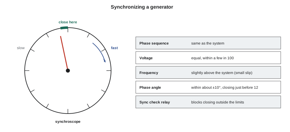
A generator cannot simply be switched onto a live system. Before its breaker closes, four conditions must be met:
- Phase sequence the same as the system's, confirmed when the generator is first connected or after any work on its connections.
- Voltage equal to the system voltage, within a small tolerance, typically a few in 100, so that little reactive current flows at closing.
- Frequency very slightly above the system's, so that the generator picks up a little load rather than motoring. The difference is the slip.
- Phase angle close to zero: the generator's voltage waveform must line up with the system's at the instant the breaker closes, usually within about ±10°.
A synchroscope shows the phase angle as a pointer that rotates once for each cycle of slip: clockwise, the fast direction, when the generator is faster than the system, anticlockwise when it is slower. The operator, or an automatic synchronizer, adjusts the turbine speed until the pointer turns slowly in the fast direction and the voltages match, then closes the breaker just before the pointer reaches the twelve o'clock position, so that the breaker's mechanical closing time brings the contacts together at zero. A synchronism check relay blocks the breaker from closing unless voltage, slip and angle are all within their limits. Closing far out of phase applies an enormous torque to the shaft and coupling and can damage the generator, the turbine and the transformer.
Worked problem
Reading the synchroscope
During a start, the generator runs at 60.05 Hz against the system's 60.00 Hz. How long does the synchroscope pointer take to make one revolution, and how many degrees does it move per second? If the breaker takes 0.1 s to close, how far before twelve o'clock should the close signal be given?
Show solution
- Slip and period:
- \[\text{slip} = 60.05 - 60.00 = 0.05 \text{ Hz} \qquad T = \frac{1}{0.05} = 20 \text{ s per revolution}\]
- Rate of movement:
- \[\frac{360^\circ}{20 \text{ s}} = 18^\circ \text{ per second}\]
- Advance for the breaker closing time:
- \[18 \times 0.1 = 1.8^\circ\]
Answer: At 0.05 Hz slip the pointer creeps round once every 20 seconds, which gives the operator plenty of time. Automatic synchronizers calculate the advance from the measured slip and the breaker's closing time; an operator closing by hand starts the close a little before twelve o'clock and never closes with the pointer spinning fast or turning backwards.
Running in parallel
Once synchronized to a large grid, the generator's speed and frequency are fixed, and its voltage is held close to the grid's. What the operator can change is how much real and reactive power it delivers, and the two are controlled separately:
- Real power is controlled by the turbine: opening the governor valves adds steam, which advances the rotor's magnetic field slightly ahead of the system, the load angle, and the generator delivers more megawatts. Lesson 3 covered how the governor does this.
- Reactive power is controlled by the excitation: raising the field current makes the generator's internal voltage higher than the system's, so it delivers more vars; lowering it makes it deliver fewer or absorb them. The terminal voltage changes only slightly, because the grid holds it.
That is what Okonkwo watched on October 28. Raising the voltage set point raised the field current, which raised the reactive output; the megawatts did not change because the governor valves did not move.
The capability curve
A generator's capability curve shows the combinations of real and reactive power it can carry continuously. Its boundaries come from different limits: at high lagging vars, the rotor field current limit, because the field winding heats; in the middle, the stator current limit, a circle of constant apparent power, because the stator winding heats; at the right, the turbine's real power limit; and at leading power factors, the stator core end heating and stability limits, because an underexcited generator has a weaker magnetic grip on the system and its core ends run hot. The curve shifts with cooling: an air-cooled generator's capability falls when its cooling water is warm, a hydrogen-cooled one's rises with hydrogen pressure.
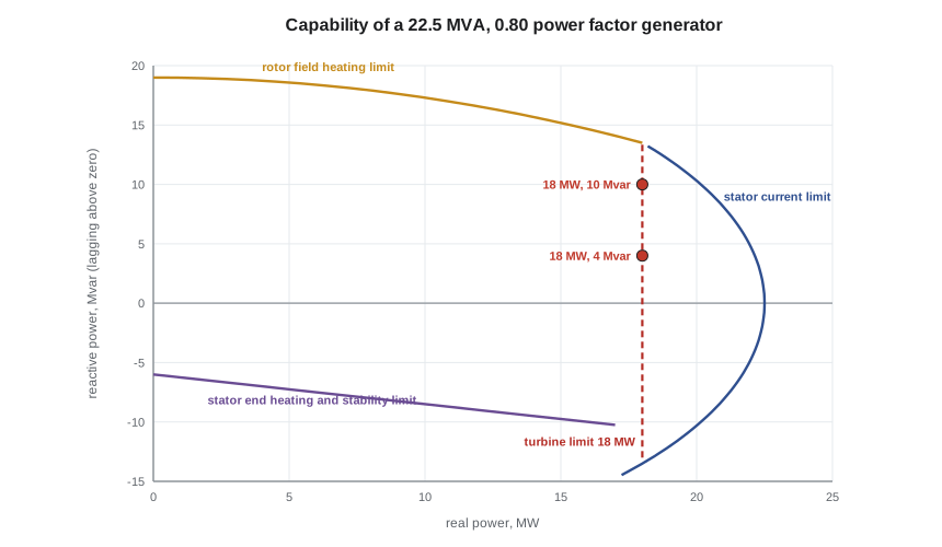
Operators keep the operating point well inside the curve, and grid operators' requests for vars are always limited to what the generator's capability allows. Ontario's market rules require generators of Keswold's size to be able to supply and absorb reactive power over a stated power factor range, and to respond to voltage requests; Keswold's interconnection agreement sets the details.
Generator protection
Generators are protected by relays that detect faults inside and outside the machine and act through the generator breaker, the excitation and, through the sequential tripping of lesson 6, the turbine. The main protections are:
- Stator differential, comparing the current entering and leaving each phase winding, which detects internal short circuits and trips immediately.
- Stator earth fault, detecting a fault from a winding to the core; generators are earthed through a high impedance so that such a fault does little damage before it is cleared.
- Loss of field, negative sequence (for unbalanced loading, which induces currents that heat the rotor surface) and reverse power.
- Overvoltage, volts per hertz, under and over frequency, and backup protection against system faults that the transmission protection fails to clear.
- Rotor earth fault detection on the field winding, and temperature monitoring of the stator windings, cooling air or gas and bearings.
Direct current generators
Direct current generators now appear mainly as old exciters and in a few special services, but the Third Class syllabus still lists them. A DC generator has a stationary field and a rotating armature whose alternating output is turned into direct current by a commutator. Its field may be separately excited from another source, or self-excited: a shunt generator has its field across the armature, so its voltage falls somewhat with load; a series generator has its field in series with the load, so its voltage rises with load; and a compound generator has both windings, arranged so that the series field makes up the shunt generator's voltage drop. Brushes and commutators need regular inspection for wear and sparking, which is one reason brushless exciters replaced DC exciters.
At about eight o'clock the grid operator released its request, and Liesl lowered the voltage set point back. Okonkwo noted the readings for his own records: 18.0 MW throughout, reactive output from 4 to 10 Mvar and back, stator current from about 770 to 860 A and back, field current up and down with it. He also noted that the cooling air leaving the generator's coolers had barely moved, which Liesl said was what she expected at that loading, and what she watched for on summer afternoons, when the cooling water was warmer and the capability smaller.
Common mistakes
MistakeExpecting raised excitation to increase a grid-connected generator's megawatts.
InsteadExcitation controls reactive power; real power comes from the turbine through the governor.
MistakeCalculating generator current from real power alone.
InsteadCurrent depends on apparent power: I = S ÷ (√3 V_L), with S = √(P² + Q²).
MistakeClosing the generator breaker with the synchroscope turning in the slow direction.
InsteadThe generator should run slightly fast, so the pointer turns slowly in the fast direction, and close just before twelve o'clock.
MistakeThinking an underexcited generator is safer because its current is lower.
InsteadUnderexcitation weakens the generator's hold on the system and heats the stator core ends; it is limited by the underexcitation limiter.
MistakeMixing up the speed formula.
InsteadN = 120f ÷ p: a two-pole machine runs at 3,600 r/min and a four-pole at 1,800 r/min on 60 Hz.
Summary and key terms
- A synchronous generator's frequency is fixed by its speed and poles, N = 120f ÷ p; steam turbine generators have cylindrical two-pole rotors.
- Apparent power S = √3 V_L I_L, with P = S cos φ and Q = S sin φ; stator heating depends on S.
- The excitation system and AVR control field current; brushless, static and DC exciters are common, with limiters and stabilizers.
- Synchronizing needs matching phase sequence, voltage, a small positive slip and a near-zero phase angle, checked by a sync check relay.
- In parallel, the turbine controls real power and the excitation controls reactive power, within the capability curve.
- Generators are protected against internal faults, loss of field, unbalance, reverse power, overfluxing and system faults.
- Synchronous generator
- An AC generator whose speed is locked to the system frequency by its magnetic field.
- Excitation system
- The equipment that supplies and controls a generator's field current.
- Brushless exciter
- A shaft-mounted alternator and rotating rectifier that supply the field without slip rings.
- Automatic voltage regulator
- The control that adjusts field current to hold generator terminal voltage.
- Synchroscope
- An instrument showing the phase angle and slip between a generator and the system.
- Slip
- In synchronizing, the frequency difference between the generator and the system.
- Capability curve
- The chart of real and reactive power combinations a generator can carry continuously.
- Power system stabilizer
- An excitation control function that damps electromechanical oscillations between generators.
- Loss of field
- Failure of a generator's excitation, causing it to lose synchronism and draw reactive power.
- Compound generator
- A DC generator with both shunt and series field windings.
Practice problems
Work each problem on paper first, then reveal the answer to check.
Find the current of a generator delivering 30 MW and 12 Mvar at 13.8 kV.
Show answer
S = 32.3 MVA; I = 32.3 × 10⁶ ÷ (√3 × 13,800) = 1,351 A.
What is that generator's power factor?
Show answer
30 ÷ 32.3 = 0.929.
A synchroscope turns once every 12 s. Find the slip and the angle moved per second.
Show answer
1 ÷ 12 = 0.083 Hz; 30° per second.
At what speed must a four-pole generator turn on a 60 Hz system?
Show answer
120 × 60 ÷ 4 = 1,800 r/min.
Lesson quiz · 5 questions
Score 60% or more to complete this lesson.
Create a free account to save your progress, take quizzes and earn a certificate.