
PWR-320 · Lesson 2 of 12 · 27 min
Turbine construction: rotors, blades and casings
▶ Video coming soon A video version of this lesson is on the way.
By Thursday, September 24, 2026, the fourth day of Keswold's fall outage, the steam turbine had been taken apart. The upper half of the casing hung from the overhead crane for an hour on Wednesday before being set down on timber cribbing at the side of the hall, and on Thursday morning the rotor itself came out, lifted level on a spreader beam and lowered onto padded stands. Okonkwo came in on his day off at Anselm's invitation and spent the day with Ingeborg Haverlund, Keswold's reliability engineer, who was running the inspection with the turbine manufacturer's field engineer.
"You will never see a turbine like this again unless you work in one of these places," Ingeborg said, handing him a hard hat with a face shield clipped to it. "So look at everything. Every part you can see has a job and a way of failing." She started with the empty lower casing, because the casing is what holds the rest in place.
This lesson describes the parts of a multistage steam turbine: the casing and how it is supported, the diaphragms and fixed blades, the rotor and its moving blades, the packing that controls leakage, and the bearings that carry and locate the rotor. It works the centrifugal force on a long blade and the thermal growth of a casing, and it ends with what the Keswold inspection found.
The casing
The casing contains the steam, carries the nozzles and diaphragms, and forms the passages that lead steam in and out. Almost all turbine casings are split horizontally at the shaft centreline, with heavy bolted flanges, so that the upper half can be lifted off and the rotor removed. On large turbines the flange bolts are tightened by heating them: a bolt heater is inserted into a hole bored down the bolt's centre, the bolt stretches, the nut is run down a measured amount, and the bolt is allowed to cool and shrink. The amount of stretch, measured with a micrometer or by nut rotation, sets the preload far more accurately than a torque wrench could.
The high-pressure end of the casing must hold the full inlet pressure and temperature, so it is a thick steel casting, usually a chromium-molybdenum alloy that keeps its strength and resists creep at high temperature. Large high-pressure turbines use a double shell: an inner casing holding the nozzles and diaphragms inside an outer casing, with steam at an intermediate pressure in the space between. Each shell then carries only part of the pressure difference, so both can be thinner and heat up more evenly. The low-pressure end of a condensing turbine carries only vacuum and must be large, because the exhaust steam has an enormous volume; it is usually fabricated from welded steel plate. Its exhaust hood turns the steam down into the condenser.
At low loads the last stages of a condensing turbine do little work and can actually churn the steam, heating it, a condition called windage. The exhaust hood can overheat. Exhaust hood sprays inject condensate into the hood automatically when its temperature rises above a set point, typically around 80 °C (175 °F), and a high exhaust temperature trip protects the hood and the last stage blades if the sprays cannot cope.
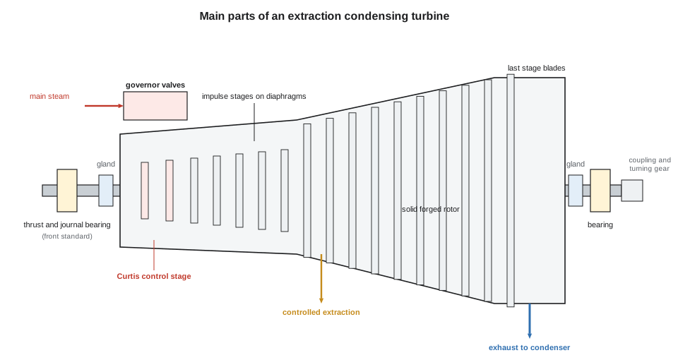
Keswold's turbine has a single casing: a cast chromium-molybdenum section from the inlet to the extraction, bolted at a vertical flange to a fabricated low-pressure section and exhaust hood. Ingeborg pointed out the inlet steam chest on top, with its four governor valves, and the nozzle boxes underneath, each one feeding an arc of the Curtis control stage.
Supporting a casing that grows
A turbine casing heats from room temperature to several hundred degrees at its inlet end and grows accordingly. If it were bolted rigidly to its foundation it would buckle, lift itself off its supports, or push the rotor out of line. Turbine casings are therefore supported so that they can grow freely in every direction while staying centred on the rotor.
- The casing is supported at or near its horizontal centreline, on palms or paws that rest on the bearing pedestals. As the casing heats it grows upwards and downwards about its centreline equally, so the centreline does not move vertically.
- A fixed point or anchor, usually at the exhaust end of a condensing turbine where the casing is coolest and largest, holds one point of the casing in place. The rest of the casing grows away from it.
- Keys and guides let the casing slide along its axis and keep it centred sideways. The pedestal at the high-pressure end, the front standard, is often mounted on a sliding base so that it moves with the casing.
- Steam pipes connected to the casing must have flexibility built into them so that they do not push the casing out of position; large pipe forces are one of the most common causes of turbine misalignment and vibration.
Worked problem
Growth of Keswold's casing
The distance from Keswold's casing anchor at the exhaust end to the high-pressure end is about 4.0 m. On average the casing heats by about 400 K from cold. The coefficient of expansion of the casing steel is about 12.5 × 10⁻⁶ per K. How far does the high-pressure end move?
Show solution
- Thermal growth:
- \[\Delta L = \alpha L \Delta T = 12.5 \times 10^{-6} \times 4{,}000 \times 400 = 20 \text{ mm}\]
Answer: The high-pressure end moves about 20 mm towards the front of the machine as it warms. The front standard slides with it, and indicators on the sliding base let the operators check that it is moving freely during startup. A casing that stops growing smoothly, or grows in jerks, is sticking on its keys.
Diaphragms and fixed blades
In an impulse turbine each stage's nozzles are held in a diaphragm, a steel disc with a ring of nozzle passages near its rim and a hole in the middle for the shaft. Diaphragms are split horizontally like the casing, and each half sits in a groove machined in its casing half. The diaphragm must hold the pressure difference across its stage, so it is a thick, stiff part, and it must be centred precisely on the rotor. Where the shaft passes through it, interstage packing limits the steam that leaks from one stage to the next without passing through the nozzles.
In a reaction turbine there are no diaphragms. The fixed blades are mounted in blade rings or carriers attached to the casing, and the moving blades on a drum-shaped rotor, with seals at the tips of both rows. Because a reaction stage has a pressure drop across its moving blades, steam leaks past the blade tips, so reaction turbines need tight tip clearances and fine seals.
The rotor
The rotor carries all of the moving blades and transmits the turbine's torque to the generator. Three types are common:
- Solid forged or monoblock rotors are machined from a single forging, with the discs or drum part of the shaft. They are used for most modern high-pressure rotors and for Keswold's whole rotor.
- Built-up rotors have separate discs shrunk onto a shaft and keyed in place. They were common in older and low-pressure turbines; the shrink fits and keyways are places where stress corrosion cracking can start, especially in wet steam.
- Welded rotors are built from forged discs welded together into one piece, which avoids the very large single forgings needed for big low-pressure rotors.
High-pressure rotors are made from creep-resistant chromium-molybdenum-vanadium steel; low-pressure rotors, which are cooler but larger and more highly stressed, from nickel-chromium-molybdenum-vanadium steel, which is tougher at low temperature. Older forgings often have a hole bored down their centre to remove the impure core of the ingot and to allow the bore to be inspected; modern forgings are clean enough to be made solid. Every rotor has places for balance weights at several planes along its length, and a coupling flange at the generator end.
A rotor that sits still while hot will bow, because its top half cools differently from its bottom half and it sags under its own weight. A bowed rotor rubs its seals and vibrates badly when it is started. That is why every large turbine has a turning gear, also called barring gear: an electric motor that turns the rotor slowly, a few revolutions per minute, whenever the turbine is shut down hot and before it is started. Lesson 5 explains how long it must run.
Moving blades
A turbine blade has three parts: the root, which fixes it to the rotor; the aerofoil or vane, which does the work; and usually a shroud or cover at its tip. The root must carry the centrifugal pull of the blade, which in the last stages is enormous.
- Root forms include the T-root and dovetail, which slide into a circumferential groove around the rotor; the fir-tree root, with several lobes on each side, which slides into an axial slot; and the pinned fork root, which straddles a disc rim and is held by pins through both.
- Shrouds join the blade tips in groups, stiffening them against vibration and forming a seal surface. They are fixed by tenons on the blade tips that are riveted over, or are integral with each blade and touch the next. Long blades may also have a lashing wire or snubber partway along to damp vibration.
- Short high-pressure blades are nearly straight and of constant section. Long low-pressure blades are twisted and tapered, because the blade speed rises from root to tip; the twist matches the blade angle to the steam angle all the way along, a design called free vortex.
Blades are usually made of 12 chromium stainless steel, which combines strength, toughness and resistance to corrosion. Some of the longest last-stage blades in large turbines are titanium alloy, which is lighter for the same strength.
Worked problem
The pull of a last-stage blade
Each blade of Keswold's last stage has a mass of about 6.5 kg, with its centre of mass at a radius of 0.95 m. The rotor turns at 3,600 r/min. Find the centrifugal force on the blade root, and compare it with the blade's weight. The blade tip diameter is 2.4 m; find the tip speed.
Show solution
- Angular velocity:
- \[\omega = \frac{2\pi \times 3{,}600}{60} = 377.0 \text{ rad/s}\]
- Centrifugal force, F = mω²r:
- \[F = 6.5 \times 377.0^2 \times 0.95 = 877{,}600 \text{ N} \approx 878 \text{ kN}\]
- Compared with the weight, ω²r ÷ g:
- \[\frac{377.0^2 \times 0.95}{9.81} \approx 13{,}760\]
- Tip speed:
- \[v = \frac{\pi \times 2.4 \times 3{,}600}{60} = 452 \text{ m/s}\]
Answer: Each blade root carries close to 880 kN, the weight of about 90 tonnes, nearly fourteen thousand times the blade's own weight. The tip moves at 452 m/s, well above the speed of sound in air. A small crack at the root, a little loss of material from erosion on one blade, or a few per cent of overspeed all matter at these forces, which is why blades are inspected so carefully and why overspeed protection is the most important trip on the machine.
Because centrifugal force rises with the square of speed, a 10 in 100 overspeed raises the force on every blade root by 21 in 100. Rotors are designed and spin-tested at the factory to survive a margin above their trip speed, but not much more.
Packing and glands
Wherever the rotor passes through a diaphragm or the casing wall, steam would leak along the shaft without a seal. Turbines use labyrinth packing: rings of sharp-edged teeth, set very close to the shaft or to raised lands on it, that make the steam pass through a series of tiny gaps and expansion chambers. Each gap throttles the steam a little, so the pressure falls in many small steps and the leakage is small. The packing rings are made in segments held against the shaft by springs, so that if the rotor rubs during startup the segments are pushed back rather than ground away. Spill strips are thin fins on the diaphragms or casing that seal over the blade shrouds.
At the ends of the casing, the shaft glands have a harder job. At the high-pressure end, steam leaks outwards; at the exhaust end of a condensing turbine, air would leak inwards into the vacuum. A gland sealing steam system solves both. Steam at a little above atmospheric pressure is supplied to a chamber in each gland. At the exhaust end it fills the gland so that only steam, not air, can be drawn into the turbine. At the high-pressure end, leakage from inside the turbine feeds the gland, and once the turbine is loaded it supplies enough steam to seal the exhaust end as well: the turbine becomes self-sealing. The outermost chambers of each gland are connected to a gland steam condenser, a small heat exchanger cooled by condensate, with an exhauster fan that holds them slightly below atmospheric pressure so that no steam escapes into the turbine hall.
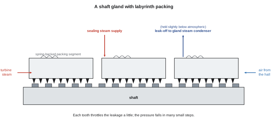
Small mechanical-drive turbines such as Cantwell's feed pump turbine use carbon ring glands instead, as PWR-230 described; a visible wisp of steam from the leak-off is normal on those machines but should never be seen at a large turbine's glands.
Bearings and thrust
Large turbine rotors run in journal bearings lined with white metal (babbitt) and lubricated under pressure. Many are tilting pad bearings, with several pads that pivot so that each forms its own oil wedge; they resist the oil whirl instability that plain cylindrical bearings can suffer at high speed. The thrust bearing, usually a tilting pad (Kingsbury or Michell) type acting on a collar on the shaft, carries the axial thrust and fixes the rotor's axial position. Because the rotor and casing grow by different amounts as they heat, the thrust bearing's position sets where the clearances are tightest, which is usually at the high-pressure end.
Impulse stages produce little thrust, because the pressure is the same on both sides of their moving blades, but the pressure difference across each disc and the change in flow velocity still push the rotor towards the exhaust. Reaction stages produce much more, because every moving row has a pressure drop across it. Reaction turbines use a balance piston (or dummy piston), a large-diameter section of the rotor at the inlet end with labyrinth seals, with high-pressure steam on one side and a line to a lower-pressure stage on the other, sized so that its thrust opposes the blading's. Double-flow low-pressure casings, with steam entering in the middle and flowing outwards both ways, balance their own thrust.
Thrust bearing wear is serious because the rotor's axial clearances are small. Deposits on the blades increase the thrust, and a sudden flow of water into the turbine, called water induction, can produce enormous thrust in an instant. Every large turbine has a thrust position monitor, usually proximity probes reading the collar's position, with alarm and trip settings a fraction of a millimetre from normal.
What the inspection found
By the end of the day the inspection team had a list. The Curtis wheel and the first few stages carried a thin tan deposit, which a sample later showed was mostly silica with some iron oxide; it was not thick enough to affect performance, but Ingeborg added a note to review the HRSG's steam purity results with the water treatment supplier. The leading edges of the last-stage blades showed the familiar frosted erosion of wet steam, worst near the tips, still well within the manufacturer's limits; the hardened shields on those edges had been replaced at the previous major inspection. Two segments of interstage packing at stage 9 were worn to about twice their design clearance, with polish marks that showed a rub, probably during a hot restart the previous winter, and were replaced. The blade roots and the rotor's accessible surfaces were cleaned by blasting with a mild abrasive and examined by magnetic particle testing, which found no indications.
The thrust bearing pads showed normal wear. A borescope inspection of the main stop valves found one strainer screen with a torn corner, which was replaced. The rotor would be balanced at low speed in the manufacturer's shop before going back in, because two packing lands had been machined.
Okonkwo asked Ingeborg how she decided what was worth fixing. "The manufacturer gives limits for everything we measure: clearances, erosion depth, crack indications, deposit thickness," she said. "Inside the limits we record it and trend it. Outside them we repair or replace. And anything we can't explain goes to the manufacturer's engineers before we close the casing." The rotor went back into the casing on Monday, October 12, the upper casing was lowered and bolted on Tuesday, October 13, and the rotor went onto turning gear on Wednesday, October 14.
Common mistakes
MistakeThinking a turbine casing is bolted rigidly to its foundation.
InsteadCasings are supported at the centreline from a fixed point, with keys and guides so that they can grow freely while staying centred.
MistakeExpecting centrifugal force on a blade to rise in proportion to speed.
InsteadF = mω²r rises with the square of speed: 10 in 100 overspeed means 21 in 100 more force.
MistakeAssuming a visible steam plume at a large turbine's gland is normal.
InsteadLarge turbines seal their glands with sealing steam and a gland steam condenser and exhauster; visible leakage means a fault.
MistakeThinking impulse turbines need a balance piston.
InsteadBalance pistons offset the large thrust of reaction blading; impulse stages produce little, and the thrust bearing carries it.
MistakeLeaving a hot rotor stationary after a shutdown.
InsteadA hot rotor bows if it is not kept turning; turning gear must run until the rotor has cooled or is restarted.
Summary and key terms
- Casings are horizontally split, with bolts preloaded by controlled heating; high-pressure parts are cast alloy steel, low-pressure exhausts fabricated.
- Casings are supported at their centreline from a fixed point and slide on keys and guides as they grow.
- Impulse turbines hold their nozzles in diaphragms with interstage packing; reaction turbines use blade carriers and tight tip seals.
- Rotors are solid forged, built-up or welded; turning gear keeps a hot rotor from bowing.
- Blades have roots, aerofoils and shrouds; long last-stage blades carry enormous centrifugal forces and suffer wet steam erosion.
- Labyrinth packing and gland sealing steam control leakage; the thrust bearing fixes the rotor's axial position.
- Diaphragm
- A split disc holding the nozzles of an impulse stage and carrying the pressure difference across the stage.
- Double shell casing
- A high-pressure casing with an inner shell inside an outer shell, each carrying part of the pressure difference.
- Exhaust hood spray
- Water sprayed into a condensing turbine's exhaust hood to cool it at low loads.
- Labyrinth packing
- A seal of many sharp-edged teeth close to the shaft that throttles leakage steam in steps.
- Gland sealing steam
- Low-pressure steam supplied to the shaft glands to keep air out of a condensing turbine.
- Turning gear
- A motor drive that turns a shut-down rotor slowly to keep it from bowing.
- Thrust bearing
- The bearing that carries the rotor's axial thrust and fixes its axial position.
- Balance piston
- A large-diameter seal section on a reaction turbine rotor arranged so that steam pressure on it opposes the blade thrust.
- Shroud
- A band joining the tips of a group of blades to stiffen them and seal over their tips.
- Windage
- Heating of steam by blades that are churning it rather than taking work from it, as in the last stages at low load.
Practice problems
Work each problem on paper first, then reveal the answer to check.
A blade of 4.0 kg has its centre of mass at 0.70 m radius. Find the centrifugal force at 3,600 r/min.
Show answer
4.0 × 377.0² × 0.70 = 398,000 N, about 398 kN.
By what factor does the force in the previous question rise at 3,960 r/min?
Show answer
(3,960 ÷ 3,600)² = 1.21.
A casing section 2.5 m long heats by 300 K, α = 12.5 × 10⁻⁶ per K. Find its growth.
Show answer
12.5 × 10⁻⁶ × 2,500 × 300 = 9.4 mm.
Why are casing flange bolts on large turbines tightened by heating rather than with a torque wrench?
Show answer
Measured stretch gives a much more accurate preload than torque, which depends on thread friction.
Lesson quiz · 5 questions
Score 60% or more to complete this lesson.
Create a free account to save your progress, take quizzes and earn a certificate.