
PWR-320 · Lesson 6 of 12 · 21 min
Turbine protection and trips
▶ Video coming soon A video version of this lesson is on the way.
On Monday, October 19, 2026, two days before the planned steam roll, Keswold's turbine was put through its trip tests. With steam isolated and the rotor on turning gear, Liesl Brannagan and an instrument technician worked through a checklist of every protective device on the machine while Okonkwo kept the log: each test, each set point found, each valve stroke time. Anselm signed the sheet at the end of each section. "After an outage this is the most important day," he said. "Every one of these was disconnected, opened up, removed or recalibrated in the last month. We prove every one before steam goes near the turbine."
This lesson describes how a turbine is protected: the trip system and why it is kept separate from the control system, the conditions that trip a turbine, the overspeed protection that matters more than any other, the role of the generator breaker and the extraction non-return valves, and how protection is tested. It works an example showing how quickly a turbine would overspeed if its valves did not close.
What a trip does
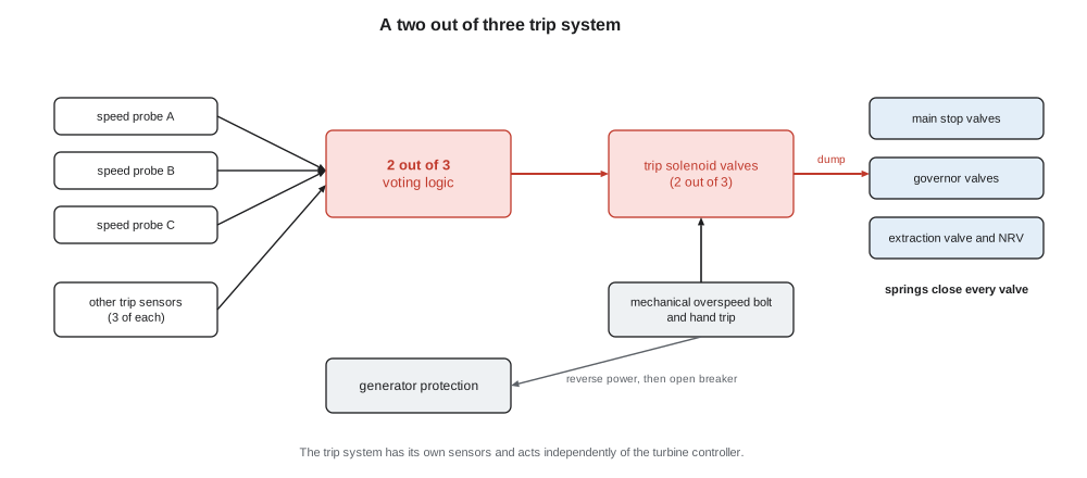
A turbine trip stops the steam supply as fast as possible. The main stop valves (also called trip valves or emergency stop valves) and the governor valves slam shut, the extraction non-return valves close, and on a reheat turbine the reheat stop and intercept valves close as well. On most modern turbines the valves are held open by hydraulic pressure against powerful springs; the trip system releases that pressure, and the springs close the valves. The trip is therefore fail-safe: anything that removes the hydraulic pressure, including a burst hose or a failed pump, closes the valves.
The trip signal comes from the trip system, which is physically separate from the control system described in lesson 3. It has its own sensors, its own logic, often built as a safety-rated system, and its own final elements, the trip solenoid valves that dump the hydraulic fluid. Its logic is usually two out of three: three independent sensors for each important trip, any two of which must agree, so that one failed sensor neither trips the turbine needlessly nor prevents a real trip. The solenoids themselves are often arranged two out of three or in pairs, so they can be tested one at a time while the turbine runs. A mechanical hand trip lever on the front standard, and trip pushbuttons in the control room, act directly on the same trip circuit.
The conditions that trip a turbine
Every turbine has its own list, set by the manufacturer and the plant's risk assessment. Keswold's steam turbine trips on:
- Overspeed, by the electronic overspeed system and, independently, by the mechanical overspeed bolt.
- Low lubricating oil pressure, after the auxiliary and emergency pumps have had a chance to start (lesson 4).
- Low control fluid pressure, because the valves could no longer be held or controlled.
- Low condenser vacuum, because a rising exhaust pressure overloads and overheats the last stages and can rupture the exhaust hood's relief diaphragms.
- High exhaust hood temperature, protecting the last stages and hood from windage heating.
- Thrust bearing position, when the rotor moves axially beyond a limit, showing thrust bearing failure.
- Differential expansion, rotor long or rotor short.
- High shaft vibration, on two adjacent probes or with a time delay, to avoid trips from a single faulty probe.
- High HRSG drum level, which risks carrying water into the steam, and low main steam temperature, both as water induction protection.
- Generator protection, such as stator differential, loss of excitation, and the generator breaker opening while the turbine is loaded.
- Loss of speed signals, and the manual trips.
Many of the same measurements have alarms set inside the trip values, to warn the operator in time to act. A trip should rarely come as a surprise: in a well-run plant, the operators have usually seen the alarm, the trend and the reason before the trip happens.
Overspeed
Overspeed is the most dangerous failure a turbine can suffer. Lesson 2 showed the centrifugal force on a long blade; a turbine that overspeeds far enough sheds blades, bursts discs and can tear itself and its casing apart. The danger is greatest when a generator is suddenly disconnected from its load, a load rejection, because at that moment the turbine is admitting full-load steam with nothing to absorb its power.
Worked problem
How fast an unloaded turbine accelerates
Keswold's steam turbine and generator rotors together have a moment of inertia of about 1,500 kg·m². The unit is generating 18 MW when its breaker opens. If the steam were not cut off, how fast would the rotor accelerate, and how long would it take to reach 110 in 100 of rated speed? How much energy would be added to the rotor in that time?
Show solution
- Rated angular velocity:
- \[\omega_0 = \frac{2\pi \times 3{,}600}{60} = 377 \text{ rad/s}\]
- Angular acceleration from P = Jωα:
- \[\alpha = \frac{P}{J\omega} = \frac{18 \times 10^6}{1{,}500 \times 377} = 31.8 \text{ rad/s}^2 \approx 304 \text{ r/min per second}\]
- Time to gain 10 in 100, 37.7 rad/s:
- \[t = \frac{37.7}{31.8} = 1.2 \text{ s}\]
- Kinetic energy at rated and at 110 in 100 of speed:
- \[E_0 = \tfrac12 \times 1{,}500 \times 377^2 = 106.6 \text{ MJ} \qquad E_{1.1} = 1.21 \times 106.6 = 129.0 \text{ MJ}\]
Answer: In a little over one second the rotor would pass its trip speed, gaining about 22 MJ of energy, and in a few more it would reach speeds at which it could fail. The valves must therefore close in a fraction of a second. Even after they close, the steam already inside the casing, the steam chest and the extraction piping keeps expanding through the turbine and drives the speed up further, which is why extraction non-return valves matter as much as the main valves.
Because of that arithmetic, turbines have several layers of overspeed protection:
- The governor itself, which closes the valves when speed rises after a load rejection; on large units an overspeed protection controller closes the governor and intercept valves momentarily at about 103 in 100.
- The electronic overspeed trip, with its own three speed probes, set typically at about 110 in 100 of rated speed, at Keswold 3,960 r/min.
- The mechanical overspeed trip: a spring-loaded bolt or eccentric weight in the shaft that flies out against its spring at the trip speed and strikes a trip lever, dumping the hydraulic fluid. It needs no power and no electronics.
Sequential tripping is the other half of overspeed protection. For most turbine and boiler trips, the turbine valves close first while the generator stays connected to the grid; the generator briefly draws power from the grid as a motor, a reverse power relay detects this and only then opens the breaker. The turbine never sees a load rejection with steam in it. Only electrical faults that require the generator to be disconnected immediately open the breaker first, and then the turbine trips at the same moment.
Extraction non-return valves
Lesson 1 noted that an extraction line holds a large volume of steam that would flow back into the turbine after a trip. Extraction lines are fitted with non-return valves that close on reverse flow; on generator turbines they are power-assisted, with a spring or air cylinder that closes them positively when the trip system acts, rather than waiting for the reverse flow to swing them shut. A heater or process line with a large volume behind it may have two in series. Their freedom to move and their closing time are tested regularly, because a valve that has seized open does nothing until the day it is needed.
Testing protection
Protection that is not tested cannot be trusted. Turbine protection is tested in several ways:
- Valve tests at load: each stop valve and governor valve is stroked closed and reopened, one at a time, while the turbine carries load, proving that it is free to close. Keswold tests its stop valves weekly and its governor valves monthly.
- Trip channel tests: each of the three channels of a two out of three trip is tripped on its own while the others hold, and each trip solenoid is tested individually, proving the logic and the final elements without tripping the turbine.
- Pressure switch and transmitter tests: each oil pressure, vacuum and similar trip sensor is tested by bleeding its pressure through a test valve until it acts, recording the set point and checking that the pumps start in the right order.
- Oil injection tests of the mechanical overspeed bolt at rated speed: oil is injected into the bolt's chamber so that it flies out at normal speed, proving it is free, while a blocking device stops it from actually tripping the turbine.
- Actual overspeed tests, in which the turbine is run up past rated speed until the trip acts, carried out after the overspeed devices have been disturbed, after a major overhaul, and at intervals the manufacturer specifies. Lesson 12 describes Keswold's.
Every trip that must be bypassed for testing or maintenance is bypassed under a written permit, with a stated duration and compensating measures, such as an operator stationed at the hand trip. A bypassed trip that is forgotten is one of the classic causes of turbine disasters.
Monday's tests
Okonkwo's log for October 19 recorded the results. With the AC main oil pump running and the bearing header at its normal pressure, the technician bled pressure from the first pressure switch: the AC auxiliary pump started at the set pressure. The second switch started the DC emergency pump. The third, tested with the trip circuit armed and the stop valves held open on the hydraulic system, tripped the turbine; Liesl confirmed the stop and governor valves closed. Each switch was within its calibration tolerance. The low vacuum trip, tested with its sensing line isolated and a test pressure applied, acted at its set point on all three channels, and the high exhaust temperature thermocouples were checked against a calibrator.
The valve stroke times were timed on the control system from the trip signal to the closed position switch. Both stop valves closed in under three tenths of a second, inside the manufacturer's limit. The governor valves were slightly slower but also inside it. The extraction non-return valve's power-assisted closing cylinder, however, closed the valve noticeably more slowly than the previous recorded test. The technician traced it to a sticking air solenoid that vented the cylinder; it was replaced that afternoon, and the retest matched the earlier time. "That's why we time it," Anselm said. "It still closed. It might not have closed fast enough."
The last test of the day was the simplest. Liesl reset the trip, raised hydraulic pressure, opened the stop valves a few per cent with the turbine still isolated from steam, and asked Okonkwo to walk to the front standard and pull the hand trip lever. The valves slammed shut with a sound he felt through the floor. The electronic overspeed channels would be proven during the overspeed test on the first run; the mechanical bolt had been cleaned and reset in the outage and would be proven the same way.
After a trip
A trip ends the danger of overspeed but starts a sequence of its own that the operators must manage. The first minute decides how much harm the trip does. The board operator confirms that every steam valve has closed and that the speed is falling, because a valve that has stuck open, or a leaking extraction non-return valve, shows itself as a speed that falls more slowly than usual or begins to rise again. If it does, the operator closes the steam supply further back, at the HRSG or header isolating valves, and opens the vacuum breaker if the procedure allows. The operator then confirms that the generator breaker has opened and the excitation has been removed.
Next come the auxiliaries. The oil pumps must keep running through the coast-down, with the standby pumps ready; the gland sealing steam must be kept on while there is vacuum, or air rushes in along the shaft and cools it unevenly; the drains are opened to remove condensate from the cooling steam lines; and the turning gear must engage when the rotor stops. On a combined cycle, the HRSG's steam goes to the bypass, and the gas turbine is run back if it has not tripped as well.
Only then does the cause matter, and the rule is the same at every well-run plant: a turbine is not restarted until the reason for the trip is understood. The first-out indication on the trip system, which records which trip acted first, the alarm log and the historian trends are the evidence. A trip that cannot be explained is treated as a real fault until shown otherwise.
Common mistakes
MistakeThinking a turbine trip system is part of the governor.
InsteadThe trip system has its own sensors, logic and solenoids, independent of the control system.
MistakeOpening the generator breaker first on a normal shutdown or boiler trip.
InsteadClose the turbine valves first and let reverse power open the breaker, so the turbine never sees a load rejection with steam in it.
MistakeAssuming a non-return valve that has not been tested will close when needed.
InsteadExtraction non-return valves are tested for freedom and timed for closing, because a seized valve shows nothing until it fails.
MistakeLeaving a trip bypassed after a test.
InsteadEvery bypass has a permit, a duration and compensating measures, and is removed and recorded.
MistakeThinking two out of three voting makes a trip less likely to act.
InsteadIt makes it both more reliable and less prone to false trips: one failed sensor neither causes nor blocks a trip.
Summary and key terms
- A trip closes the stop, governor and extraction valves by releasing hydraulic pressure so that springs close them; the system is fail-safe.
- The trip system is separate from the control system and usually votes two out of three.
- Common trips include overspeed, low lube oil and control fluid pressure, low vacuum, high exhaust temperature, thrust, differential expansion, vibration and generator faults.
- An unloaded turbine at full steam accelerates past its trip speed in about a second, so valves must close in a fraction of a second.
- Overspeed protection has layers: governor action, electronic trip, mechanical bolt, and sequential tripping through reverse power.
- Protection is proven by valve tests, channel tests, pressure switch tests, oil injection and actual overspeed tests.
- Turbine trip
- The rapid closing of all steam admission and extraction valves by the protection system.
- Fail-safe
- Designed so that a failure of power or fluid moves the system to its safe state.
- Two out of three voting
- Trip logic requiring any two of three independent channels to agree.
- Load rejection
- The sudden loss of a generator's electrical load, as when its breaker opens.
- Mechanical overspeed trip
- A spring-loaded bolt or weight in the shaft that flies out at trip speed and releases the trip system.
- Sequential tripping
- Closing the turbine valves first and opening the generator breaker only after reverse power is detected.
- Reverse power relay
- A generator protection relay that detects power flowing into the generator from the grid.
- Oil injection test
- A test of the mechanical overspeed bolt at rated speed by injecting oil to make it fly out.
- Power-assisted non-return valve
- A non-return valve with an actuator that closes it positively on a trip.
Practice problems
Work each problem on paper first, then reveal the answer to check.
A rotor with J = 900 kg·m² is at 3,600 r/min carrying 10 MW when its breaker opens. Find its acceleration in rad/s².
Show answer
10 × 10⁶ ÷ (900 × 377) = 29.5 rad/s².
How long would that rotor take to gain 10 in 100 of its speed with steam still on?
Show answer
37.7 ÷ 29.5 = 1.3 s.
By what factor does a rotor's kinetic energy rise from rated speed to 110 in 100 of it?
Show answer
1.1² = 1.21.
Why does a normal turbine trip wait for reverse power before opening the generator breaker?
Show answer
So the turbine is never disconnected from its load with steam still entering it.
Lesson quiz · 5 questions
Score 60% or more to complete this lesson.
Create a free account to save your progress, take quizzes and earn a certificate.