
PWR-320 · Lesson 3 of 12 · 27 min
Turbine governors and controls
▶ Video coming soon A video version of this lesson is on the way.
While the turbine was in pieces, its controls could still be studied. On Wednesday, September 30, 2026, Ingeborg Haverlund booked Keswold's training room for an afternoon, and Liesl Brannagan, the board operator on Anselm's shift, joined them with a laptop connected to the plant historian. Liesl had run Keswold's control room for six years. "Most people think the governor holds the speed," she said. "On a turbine tied to the grid, the grid holds the speed. Our governor decides how much power we put in, and how we answer when the grid frequency moves. That's a different job."
This lesson explains what a turbine governor does before and after the generator is synchronized, how mechanical-hydraulic and electro-hydraulic governors work, the difference between droop and isochronous control, how a generator shares a change in grid load with every other generator, and how an extraction turbine holds both its power and its extraction pressure. It works examples on droop response and load sharing.
What a governor must do
A turbine's governor system controls the steam admitted to it. What it controls that steam to achieve changes with the situation:
- Before synchronizing, with the generator breaker open, the turbine has no load to hold it back, and the governor controls speed. It brings the turbine up through its warm-up holds to rated speed, then makes the small speed adjustments needed to synchronize.
- When synchronized to a large grid, the generator is locked to the grid's frequency and the turbine cannot change speed on its own. The governor now controls power output, and responds to changes in grid frequency according to its droop setting.
- On an isolated system, such as a plant running in island mode after losing its utility tie, the governor controls speed and frequency directly, and the load is whatever the connected equipment demands.
- Pressure control: a back-pressure or extraction turbine may be controlled to hold an exhaust or extraction pressure, letting the power output follow the steam demand; a turbine may also be limited by its inlet pressure so that it does not draw the boiler down.
Underneath all of these sits the protection system, described in lesson 6, which shuts the turbine down whatever the governor is doing.
Governing methods
Lesson 1 described the two ways steam flow can be varied: throttle governing, where one valve or a set of valves opened together throttles all of the steam, and nozzle governing, where valves open groups of nozzles in sequence. A third method, bypass governing, opens an extra valve at high load that admits steam to a later stage, bypassing the first stages, so that a turbine can carry an overload at reduced efficiency. Many large turbines can switch between full arc (throttle) admission for even heating during startup and partial arc (nozzle) admission for efficiency at load.
The syllabus also distinguishes governors by what they sense. A speed-sensitive governor responds to rotor speed; a pressure-sensitive governor responds to a steam pressure, usually the exhaust pressure of a back-pressure turbine or the extraction pressure of an extraction turbine. Most turbines have both, with logic that decides which is in control.
Mechanical-hydraulic governors
The classical governor uses flyweights driven from the turbine shaft. As speed rises, the weights swing outwards against a spring and move a pilot valve. The pilot valve directs oil to one side of a servomotor, or power piston, which is strong enough to move the governor valves against the steam forces. As the servomotor moves, a feedback linkage moves the pilot valve back towards its centred position, so that the valves settle at a new position rather than running to the end of their travel. That feedback is what gives the governor its droop: a new valve position, and therefore a new load, needs a slightly different speed to balance the forces.
A speed changer or synchronizer, a small motor that adjusts the spring setting, shifts the governor's whole speed-load line up or down. Before synchronizing it raises or lowers the speed; once synchronized, it raises or lowers the load, because the speed is held by the grid. Hydraulic governors of this kind, such as the Woodward designs found on many mechanical drives and older generator turbines, are still common on small machines and are often fitted with an electric actuator that lets a control system move the speed changer.
Electro-hydraulic control
Most generator turbines built or modernized in recent decades use electro-hydraulic control (EHC). The speed is measured by several magnetic or proximity speed pickups reading a toothed wheel on the shaft, usually three so that the controller can vote two out of three and keep running if one fails. A digital controller, usually redundant, compares speed, load, pressures and limits with their set points and calculates a valve position demand for each valve. Electro-hydraulic servo valves turn the controller's signal into oil flow to each valve actuator, and a linear variable differential transformer (LVDT) on each actuator reports the valve's actual position back to the controller.
The actuators need high-pressure oil to move large valves quickly against steam forces. Large utility turbines use a separate high-pressure control fluid system, often a fire-resistant phosphate ester fluid at a pressure in the order of 11,000 kPa (1,600 psi), so that a leak near the hot steam valves does not start a fire. Keswold's turbine has its own hydraulic power unit with two pumps, filters, accumulators and its own fluid; the lubricating oil system of lesson 4 is separate.
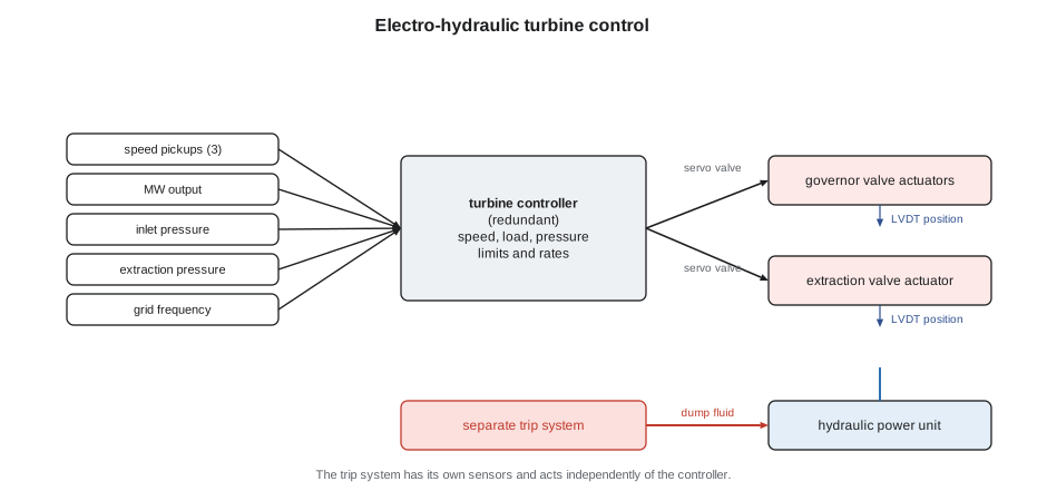
EHC makes functions possible that mechanical governors could not offer: accurate load control, automatic run-up sequences, valve testing at load, rate limits that protect the rotor from thermal stress, limits on inlet pressure and extraction flow, and fast valve closing on a load rejection. It also makes the turbine an easily adjusted part of the plant's distributed control system, which is both its strength and the reason its settings are kept under management of change.
Droop
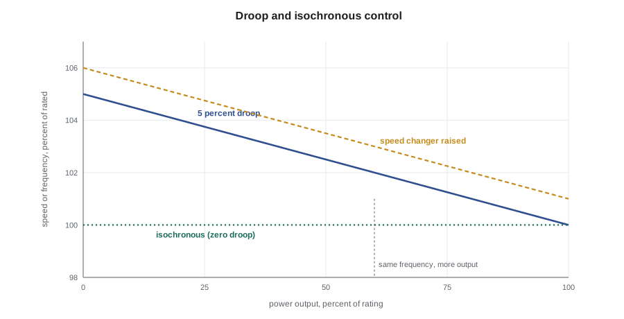
Droop, also called speed regulation, is the fall in speed from no load to full load, expressed as a fraction of rated speed, with the speed changer left alone:
A turbine set for 5 in 100 droop and running at 3,600 r/min at full load would run at 3,600 × 1.05 = 3,780 r/min if its load were removed with the speed changer untouched; the governor valves would close along a straight line from full open at 3,600 to closed at 3,780. Once synchronized to a grid, that same line describes how the turbine answers a change in frequency: every 1 in 100 change in frequency moves the output by 1 ÷ 0.05 = 20 in 100 of the rating.
Worked problem
Keswold's answer to a frequency dip
Keswold's steam turbine generator is rated at 18 MW with 5 in 100 droop. The grid frequency falls from 60.00 Hz to 59.90 Hz after a large generator elsewhere trips. Find the change in output the droop asks for, first with no deadband, then with a deadband of ±36 mHz applied without a step at its edge.
Show solution
- Frequency change as a fraction of rated:
- \[\frac{\Delta f}{f} = \frac{0.10}{60} = 0.00167\]
- Change in output with no deadband:
- \[\Delta P = \frac{0.00167}{0.05} \times 18 = 0.60 \text{ MW}\]
- With a 36 mHz deadband, only the frequency change beyond it counts:
- \[\Delta P = \frac{(0.100 - 0.036)/60}{0.05} \times 18 = 0.38 \text{ MW}\]
Answer: The governor would open the valves to add about 0.6 MW, or 0.38 MW with the deadband, within seconds, provided the turbine had that margin available. A unit already at its valve limit, or one whose plant control immediately pulls the load back to its set point, gives no lasting help, which is why grid operators check that generators actually provide this primary frequency response.
In North America the reliability standards and guidance published by NERC, which apply in Ontario through the IESO, set the expectations for this response. NERC's guidance to generator owners has called for governors with droop of no more than 5 in 100 and a deadband no wider than ±36 mHz, while leaving the exact settings to the grid operator; gas turbines are commonly set nearer 4 in 100. Keswold's settings, 5 in 100 on the steam turbine and 4 in 100 on the gas turbine, are recorded in its interconnection documents.
Load sharing
Droop is what lets many generators share a grid. When the total load rises, the frequency falls slightly, and every generator with governor response picks up a share of the increase in proportion to its rating divided by its droop. No generator has to know what the others are doing.
Worked problem
Sharing between Keswold's two units
Keswold's gas turbine generator (45 MW, 4 in 100 droop) and steam turbine generator (18 MW, 5 in 100 droop) are imagined running on their own small network with a 2.0 MW load increase and no other generators. How is the increase shared, and how far does the frequency fall? (Treat the steam turbine as able to respond without waiting for the HRSG.)
Show solution
- Each unit's response per unit of frequency fraction is its rating divided by its droop:
- \[\text{ST}: \frac{18}{0.05} = 360 \text{ MW} \qquad \text{GT}: \frac{45}{0.04} = 1{,}125 \text{ MW}\]
- Shares of the 2.0 MW:
- \[\text{ST} = 2.0 \times \frac{360}{1{,}485} = 0.48 \text{ MW} \qquad \text{GT} = 2.0 \times \frac{1{,}125}{1{,}485} = 1.52 \text{ MW}\]
- Frequency fall:
- \[\Delta f = \frac{2.0}{1{,}485} \times 60 = 0.081 \text{ Hz}\]
Answer: The gas turbine takes about three quarters of the increase because it is larger and has the steeper droop response. The frequency settles about 0.08 Hz low, and stays there until an operator, or an automatic control, raises the speed changer set points to bring it back to 60 Hz.
That last step is the difference between primary and secondary control. Droop response stops the frequency falling but leaves it low. Restoring it, by changing generators' set points, is done on a large grid by the grid operator's automatic generation control, which sends set point changes to selected generators every few seconds.
Isochronous control
An isochronous governor has zero droop: it holds speed constant whatever the load, by integrating the speed error until it is gone. It is ideal for a single generator supplying an isolated load, because the frequency stays exactly right. It cannot be used by more than one generator on the same system unless they share load through a separate load sharing control, because two isochronous governors with slightly different set points would fight, one taking all the load and the other motoring. On a large grid, isochronous control would make a generator try to correct the whole grid's frequency on its own.
Many plant control systems therefore switch modes automatically. Keswold's turbines run in droop with load control while the main breaker to the utility is closed. If that breaker opens and the plant has to carry Marrowby Foods' electrical load in island mode, which the plant tests once a year, the gas turbine's governor switches to isochronous and holds the frequency, and the steam turbine stays in droop and follows.
Controlling an extraction turbine
An automatic extraction turbine has two outputs to control, power and extraction pressure, and two sets of valves to do it with: the governor valves at the inlet, and the extraction valve, a set of valves or a rotating grid inside the casing that controls the flow from the high-pressure section into the low-pressure section. Moving either set of valves changes both outputs. If Marrowby Foods draws more steam, the extraction pressure falls; opening the inlet valves would restore it but add power, and closing the extraction valve would restore it but take power away from the low-pressure section.
The control system solves this by moving both sets of valves together in a calculated ratio, called decoupled or ratio control. To supply more extraction steam at constant power it opens the inlet valves and closes the extraction valve so that the extra steam passes through the high-pressure section only; to raise power at constant extraction it opens both. The limits on all of this are set out in the manufacturer's extraction performance diagram, or steam map, which shows the possible combinations of power, inlet flow and extraction flow, bounded by the maximum inlet flow, the maximum extraction and the minimum flow the low-pressure section needs to avoid windage overheating.
Worked problem
What Marrowby's steam costs in power
At full load Keswold's turbine passes 22 kg/s at its inlet, with 6.0 kg/s extracted and 16.0 kg/s to the condenser. The low-pressure section's actual enthalpy drop from the extraction to the exhaust is 677 kJ/kg. If the inlet flow is held constant and Marrowby takes 1.0 kg/s more extraction steam, how much power is lost?
Show solution
- The extra steam no longer passes through the low-pressure section:
- \[\Delta P = 1.0 \times 677 = 677 \text{ kW}\]
Answer: Each extra kilogram per second of process steam costs about 0.68 MW at the turbine shaft, before generator losses, unless the inlet flow is raised to make it up. That figure is the starting point for the steam price in Keswold's contract with Marrowby Foods.
Liesl pulled up a trend from a Monday morning in August when Marrowby started its cookers. The extraction flow rose steeply over about ten minutes, the extraction pressure dipped by about 20 kPa (3 psi) and recovered, the governor valves opened, and the electrical output barely moved. "That's the decoupling working," she said. "When it wasn't tuned right, before my time, the operators used to see the megawatts swing every time Marrowby changed a load."
Limiters and rates
Around the main control loops the controller applies limits. A load limiter caps the valve opening at a set value; an inlet pressure limiter reduces load if the steam supply pressure falls, so that the turbine does not drag the HRSG or boilers down; rate limits restrict how fast load and speed can change, protecting the rotor from thermal stress; a minimum exhaust flow limit protects the last stages; and at Keswold an extraction flow limit protects the extraction stage from excessive loading. Large utility turbines also have an overspeed protection controller that closes the intercept and governor valves momentarily if speed passes about 103 in 100 after a load rejection, before the trip setting is reached.
Okonkwo asked how the controller knew what was really happening if its speed pickups disagreed. Liesl showed him the diagnostic page: the three speed signals, the voted value, and an alarm that would sound if any one differed from the others by more than a few r/min. The protection system, she said, had its own separate set of probes. "The control system and the protection system never share a sensor. If they did, the failure that confuses one would blind the other."
Common mistakes
MistakeThinking a synchronized turbine's governor controls its speed.
InsteadOn a large grid the speed is fixed by the grid frequency; the governor controls power output and answers frequency changes through its droop.
MistakeCalculating droop response from the frequency change in hertz without dividing by rated frequency.
InsteadΔP = (Δf ÷ f) ÷ droop × rating.
MistakePutting two generators in parallel on isochronous control.
InsteadOnly one unit on a system can run isochronous unless a load sharing control is fitted; the rest must run in droop.
MistakeExpecting droop to restore the frequency to normal.
InsteadDroop arrests the change; set point changes by operators or automatic generation control restore it.
MistakeAdjusting only the extraction valve to supply more process steam.
InsteadThat would also change power; decoupled control moves the inlet and extraction valves together.
Summary and key terms
- The governor controls speed before synchronizing, power and frequency response when synchronized, and speed and frequency on an isolated system.
- Mechanical-hydraulic governors use flyweights, a pilot valve and a servomotor with feedback; EHC uses speed pickups, a digital controller, servo valves and LVDT feedback.
- Droop is the fall in speed from no load to full load as a fraction of rated speed; output changes by (Δf ÷ f) ÷ droop × rating.
- Generators on droop share a load change in proportion to rating divided by droop; secondary control restores the frequency.
- Isochronous control holds constant speed and suits a single unit on an isolated system.
- Extraction turbines use decoupled control of inlet and extraction valves within the limits of the extraction performance diagram.
- Droop
- The fall in speed from no load to full load, as a fraction of rated speed, at a fixed governor set point.
- Isochronous
- Governor control with zero droop, holding constant speed at any load.
- Speed changer
- The governor adjustment that shifts the speed-load line, setting speed before synchronizing and load after.
- Deadband
- A band of frequency deviation around nominal within which a governor does not respond.
- Electro-hydraulic control
- Turbine control using electronic sensing and computation with hydraulic valve actuators driven through servo valves.
- LVDT
- Linear variable differential transformer; a sensor reporting a valve actuator's position.
- Primary frequency response
- The automatic change in generator output, through governor droop, that arrests a change in grid frequency.
- Automatic generation control
- The grid operator's system that adjusts generator set points to restore frequency and scheduled interchange.
- Extraction performance diagram
- The manufacturer's chart of the allowable combinations of power, inlet flow and extraction flow for an extraction turbine.
Practice problems
Work each problem on paper first, then reveal the answer to check.
A 25 MW turbine generator has 4 in 100 droop. Find the change in output for a frequency fall of 0.15 Hz with no deadband.
Show answer
(0.15 ÷ 60) ÷ 0.04 × 25 = 1.56 MW.
A turbine runs at 3,600 r/min at full load with 5 in 100 droop. What speed would it reach at no load with the speed changer untouched?
Show answer
3,600 × 1.05 = 3,780 r/min.
Two units, 40 MW at 5 in 100 and 20 MW at 5 in 100, share a 3.0 MW increase. Find each share.
Show answer
Responses 800 and 400; shares 2.0 MW and 1.0 MW.
An extraction turbine's low-pressure section drop is 650 kJ/kg. What power is lost if 0.5 kg/s more is extracted at constant inlet flow?
Show answer
0.5 × 650 = 325 kW.
Lesson quiz · 5 questions
Score 60% or more to complete this lesson.
Create a free account to save your progress, take quizzes and earn a certificate.