
PWR-310 · Lesson 8 of 12 · 28 min
Heat transfer calculations
▶ Video coming soon A video version of this lesson is on the way.
On the night of Sunday, September 6, 2026, Okonkwo Demarest's first night back on his usual rotation, Desmond Kirwan sent him on the midnight round with a thermal camera and a clipboard. The district hot water loop had started its autumn duty a week before, and Desmond wanted readings from both plate heat exchangers to compare with their design data: 1 MW each, the boiler loop cooling from 95 to 70 °C, the district loop heating from 50 to 80 °C, with 16.4 m² of plate area. On the way back Okonkwo stopped at the deaerator, where the camera showed a bright patch on the steam supply line: the removable insulation jacket on a gate valve had been left off after a repack in the summer.
This lesson puts numbers on both observations. It covers the three ways heat moves, conduction, convection and radiation, and how to calculate each; heat flow through flat and cylindrical walls with several layers; the overall heat transfer coefficient and the effect of fouling; and the log mean temperature difference, which sizes and checks every heat exchanger in a plant, from plate exchangers to economizers.
Three modes of heat transfer
- Conduction is heat passing through a material, or between materials in contact, from molecule to molecule, with no movement of the material itself. It is how heat crosses a boiler tube wall or an insulation layer.
- Convection is heat carried by a moving fluid. In forced convection a fan or pump drives the fluid; in natural convection the fluid moves because the warmer part is lighter and rises. Convection carries heat from flue gas to tubes and from tubes to water.
- Radiation is heat carried by electromagnetic waves, mainly infrared, from any surface to any other it can see. It needs no medium and is the dominant mode in a furnace, where flame and hot gas radiate to the waterwalls, and it is a large part of the loss from any hot, bare surface.
In most real equipment all three act together, in series and in parallel. The calculation method in every case is to find the rate of heat flow for a temperature difference, exactly as Ohm's law finds a current for a voltage, and the analogy goes further: each mode has a thermal resistance, and resistances in series add.
Conduction through flat walls
Fourier's law gives the conduction through a flat wall of thickness x and area A, with faces at temperatures T₁ and T₂:
where k is the thermal conductivity of the material, in W/m·K. Metals conduct well; insulations badly, which is their purpose. Conductivity changes with temperature, and insulation manufacturers quote it at a stated mean temperature.
| Material | Thermal conductivity, typical |
|---|---|
| Copper | 390 W/m·K (2,700 Btu·in/h·ft²·°F) |
| Carbon steel | 50 W/m·K (350 Btu·in/h·ft²·°F) |
| Stainless steel | 16 W/m·K (110 Btu·in/h·ft²·°F) |
| Boiler scale (varies widely) | 1 to 3 W/m·K (7 to 20 Btu·in/h·ft²·°F) |
| Firebrick | 1.0 W/m·K (7 Btu·in/h·ft²·°F) |
| Water | 0.6 W/m·K (4 Btu·in/h·ft²·°F) |
| Calcium silicate pipe insulation | 0.055 W/m·K (0.38 Btu·in/h·ft²·°F) |
| Mineral wool board | 0.040 W/m·K (0.28 Btu·in/h·ft²·°F) |
| Still air | 0.026 W/m·K (0.18 Btu·in/h·ft²·°F) |
For several layers in series, each layer has a resistance x ÷ kA, and the total resistance is their sum. The heat flow is the overall temperature difference divided by the total resistance, and the temperature at each interface follows from the drop across each layer, the largest drop always across the layer with the largest resistance.
Worked problem
Heat loss through the deaerator insulation
The deaerator storage tank has 50 mm of mineral wool (k = 0.040 W/m·K) over its shell, which is at 105 °C. The outside of the insulation, under its aluminium jacket, is at 30 °C. Find the heat loss per square metre and for the tank's 30 m² of insulated surface. Treat the shell as a flat wall.
Show solution
- Per square metre:
- \[q = \frac{0.040 \times 75}{0.050} = 60 \text{ W/m}^2\]
- For the whole tank:
- \[Q = 60 \times 30 = 1{,}800 \text{ W}\]
Answer: About 1.8 kW, a small loss for a vessel holding many tonnes of water at 105 °C. The steel shell's own resistance is negligible: 10 mm of steel has a resistance per square metre about 6,000 times smaller than the insulation's.
Conduction through cylinders
Pipe insulation is not a flat wall. Heat flowing outward meets a growing area at each larger radius, so the temperature falls quickly near the pipe and slowly near the outside. For a cylindrical layer from inner radius r₁ to outer radius r₂, the heat flow per unit length is:
The natural logarithm comes from adding up thin rings, each with its own area. Because of it, each extra layer of insulation saves less than the one before, which is why economic insulation thickness is a balance between the cost of the insulation and the value of the heat saved.
Worked problem
Heat loss from an insulated steam main
An NPS 8 steam main (outside diameter 219.1 mm) at 185 °C carries 75 mm of calcium silicate insulation (k = 0.055 W/m·K). The insulation's outer surface is at 30 °C. Find the heat loss per metre of pipe.
Show solution
- Radii: r₁ = 109.55 mm, r₂ = 109.55 + 75 = 184.55 mm.
- \[\frac{Q}{L} = \frac{2\pi \times 0.055 \times (185 - 30)}{\ln(184.55/109.55)} = \frac{53.6}{0.522} = 103 \text{ W/m}\]
Answer: About 103 W per metre of pipe. The ratio of radii, not their difference, controls the loss.
Convection
Newton's law of cooling gives the heat carried away from a surface at T_s by a fluid at T_f:
where h is the convective heat transfer coefficient. Unlike conductivity, h is not a property of a material. It depends on the fluid, its velocity, the shape of the surface and whether the fluid is boiling or condensing. Typical ranges show why boilers and condensers work as they do:
| Situation | Typical h |
|---|---|
| Natural convection in still air | 5 to 10 W/m²·K (1 to 2 Btu/h·ft²·°F) |
| Forced convection, flue gas over tubes | 30 to 100 W/m²·K (5 to 18 Btu/h·ft²·°F) |
| Forced convection, water in tubes | 1,000 to 10,000 W/m²·K (180 to 1,800 Btu/h·ft²·°F) |
| Boiling water | 5,000 to 50,000 W/m²·K (900 to 9,000 Btu/h·ft²·°F) |
| Condensing steam | 5,000 to 100,000 W/m²·K (900 to 18,000 Btu/h·ft²·°F) |
The gas side of a boiler or economizer has coefficients a hundred times lower than the water side. The gas side therefore controls the heat transfer, which is why economizers and air heaters have fins on the gas side, and why soot on the gas side does so much harm.
Radiation
Every surface radiates energy in proportion to the fourth power of its absolute temperature. The Stefan-Boltzmann law gives the net exchange between a small surface at T_s and large surroundings at T_a:
The emissivity ε, between 0 and 1, says how well a surface radiates compared with a perfect radiator. Oxidized steel and most painted surfaces are around 0.8 to 0.95; bright aluminium jacketing is around 0.1, which is part of why jacketed insulation runs cool to the touch. Because of the fourth power, radiation becomes dominant at high temperatures: doubling a surface's absolute temperature multiplies its radiation sixteenfold.
Worked problem
The cost of a bare pipe
If the same NPS 8 main were bare, its surface would be close to the steam temperature, 185 °C. Estimate the loss per metre by radiation (ε = 0.8) and natural convection (h = 8 W/m²·K) to surroundings at 25 °C, and compare with the insulated pipe.
Show solution
- Surface area per metre:
- \[A = \pi \times 0.2191 = 0.688 \text{ m}^2\]
- Radiation, with 458.15 K and 298.15 K:
- \[q_r = 0.8 \times 5.67 \times 10^{-8} (458.15^4 - 298.15^4) = 1{,}640 \text{ W/m}^2 \;\Rightarrow\; 1{,}129 \text{ W/m}\]
- Convection:
- \[8 \times 160 \times 0.688 = 881 \text{ W/m}\]
- Total:
- \[1{,}129 + 881 = 2{,}010 \text{ W/m}\]
Answer: About 2.0 kW per metre, nearly twenty times the insulated pipe's 103 W. Running all year, each bare metre wastes about 16,700 kWh of heat, roughly 2,000 m³ of gas at the boiler's efficiency. A gate valve is equivalent to a metre or so of bare pipe, which is why Okonkwo's missing jacket was worth a work order that night.
The overall heat transfer coefficient
In a heat exchanger, heat passes from the hot fluid by convection to the wall, by conduction through it, and by convection into the cold fluid. Each step is a resistance, and for a thin flat wall they combine into an overall heat transfer coefficient U:
R_f is the fouling resistance: scale on the water side, soot or ash on the gas side, oil films in a lubricating oil cooler. Fouling layers are thin but conduct poorly, and in an exchanger with high film coefficients, like a plate exchanger, even a thin layer can cut U by a quarter or more. The exchanger's duty is then:
where ΔT_m is the mean temperature difference between the two fluids over the whole surface.
The log mean temperature difference
The temperature difference between two fluids changes along an exchanger as they heat and cool each other. The correct average for the duty equation is not the arithmetic mean but the log mean temperature difference, LMTD, found from the differences at the two ends, ΔT₁ and ΔT₂:
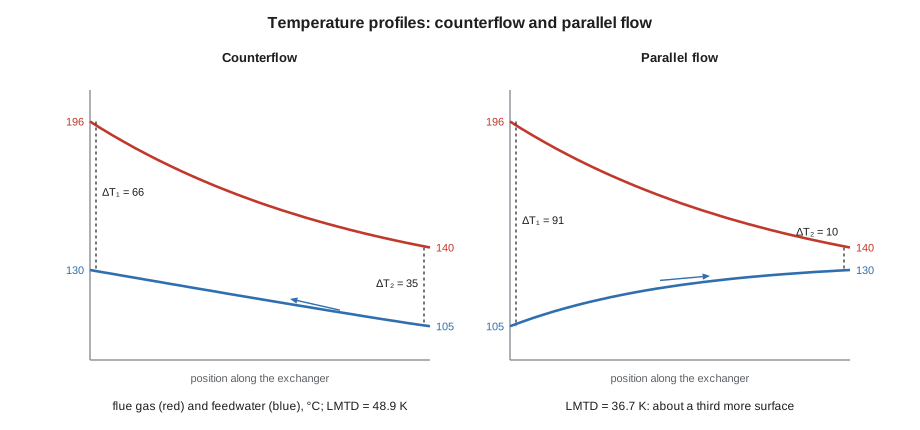
In a counterflow exchanger the fluids enter at opposite ends; in parallel flow they enter at the same end. Counterflow gives a larger LMTD for the same four temperatures and can heat the cold fluid to above the hot fluid's outlet temperature, which parallel flow never can. Most plant exchangers are counterflow or close to it; shell-and-tube exchangers with several passes use a correction factor applied to the counterflow LMTD.
Worked problem
Checking plate exchanger 1
Plate exchanger 1 is running at its design duty, 1,000 kW, with the boiler loop cooling from 95 to 70 °C and the district loop heating from 50 to 80 °C in counterflow. Its plate area is 16.4 m². Find the LMTD and the overall coefficient U.
Show solution
- End differences: at the hot inlet end, 95 − 80 = 15 K; at the hot outlet end, 70 − 50 = 20 K.
- \[\Delta T_{lm} = \frac{20 - 15}{\ln(20/15)} = \frac{5}{0.2877} = 17.4 \text{ K}\]
- Overall coefficient:
- \[U = \frac{Q}{A\,\Delta T_{lm}} = \frac{1{,}000{,}000}{16.4 \times 17.4} = 3{,}510 \text{ W/m}^2\text{·K}\]
Answer: About 3,510 W/m²·K, typical of a clean plate exchanger with water on both sides. A fouling resistance of only 0.0001 m²·K/W, a scale layer a fraction of a millimetre thick, would cut U to about 2,600, three quarters of the clean value, and the exchanger would then run with its outlet temperatures short of design. That is how the scaling in plate exchanger 2 later showed itself.
Worked problem
Why economizers are counterflow
An economizer on a boiler like boiler 2 cools flue gas from 196 °C to 140 °C while heating feedwater from 105 °C to 130 °C, transferring 147 kW. With a gas-side controlled U of about 40 W/m²·K (typical for bare tubes), compare the surface needed in counterflow and parallel flow.
Show solution
- Counterflow ends: 196 − 130 = 66 K and 140 − 105 = 35 K.
- \[\Delta T_{lm} = \frac{66 - 35}{\ln(66/35)} = 48.9 \text{ K}, \quad A = \frac{147{,}000}{40 \times 48.9} = 75 \text{ m}^2\]
- Parallel flow ends: 196 − 105 = 91 K and 140 − 130 = 10 K.
- \[\Delta T_{lm} = \frac{91 - 10}{\ln(91/10)} = 36.7 \text{ K}, \quad A = \frac{147{,}000}{40 \times 36.7} = 100 \text{ m}^2\]
Answer: Parallel flow would need about a third more surface for the same duty. Fins on the gas side raise the effective U several times and shrink the economizer further. The economizer's gas outlet must also stay safely above the flue gas dew point of lesson 10, which limits how much heat it can recover.
Back in the control room
Okonkwo's readings from exchanger 1 matched the design closely enough to give a U within a few in 100 of 3,510 W/m²·K; exchanger 2's, at a slightly different flow, came out about the same. He entered both in the log so that the next set of readings would have something to be compared with. For the valve, he wrote a work order to refit the insulation jacket, attached the thermal image, and added his estimate: about 2 kW lost for as long as the jacket stayed off. Fenella Thorncroft's crew refitted it on the Tuesday.
Common mistakes
MistakeUsing the arithmetic mean temperature difference for an exchanger.
InsteadUse the log mean temperature difference from the two end differences; the arithmetic mean overstates it.
MistakeTreating pipe insulation as a flat wall.
InsteadUse the cylinder formula with ln(r₂ ÷ r₁); the growing area changes the result.
MistakeUsing degrees Celsius or Fahrenheit in the Stefan-Boltzmann law.
InsteadRadiation uses the fourth power of absolute temperature, kelvin or degrees Rankine.
MistakeAdding conductances instead of resistances for layers in series.
InsteadAdd the resistances, 1/h and x/k, then invert to find U.
MistakeThinking more water-side velocity will fix poor gas-side heat transfer.
InsteadThe lowest coefficient controls U; improve the gas side, for example by keeping it clean or adding fins.
Summary and key terms
- Heat moves by conduction, convection and radiation; each has a thermal resistance, and resistances in series add.
- Fourier's law, Q = kAΔT ÷ x, gives conduction through a flat wall; cylinders use 2πkΔT ÷ ln(r₂ ÷ r₁) per unit length.
- Newton's law, Q = hAΔT, gives convection; h depends on the fluid and flow, and is lowest for gases.
- Radiation follows εσ(T_s⁴ − T_a⁴) and dominates at high temperature; bare hot surfaces lose heat fast.
- The overall coefficient U combines the film, wall and fouling resistances; Q = UA ΔT_lm.
- The LMTD uses the two end temperature differences; counterflow gives a larger LMTD than parallel flow.
- Conduction
- Heat transfer through a material by molecular contact, without movement of the material.
- Convection
- Heat transfer by a moving fluid, driven by a fan or pump or by natural buoyancy.
- Radiation
- Heat transfer by electromagnetic waves between surfaces that can see each other.
- Thermal conductivity
- The property of a material that sets the rate of conduction through it per unit area, thickness and temperature difference.
- Emissivity
- The ratio of the radiation from a surface to that from a perfect radiator at the same temperature.
- Overall heat transfer coefficient
- The heat transfer rate per unit area per degree of mean temperature difference between two fluids.
- Fouling resistance
- The added thermal resistance of scale, deposits or films on a heat transfer surface.
- Log mean temperature difference
- The effective mean temperature difference between two fluids in an exchanger, calculated from the end differences.
Practice problems
Work each problem on paper first, then reveal the answer to check.
A firebrick wall 230 mm thick (k = 1.0 W/m·K) has faces at 900 °C and 150 °C. Find the heat loss per square metre.
Show answer
q = 1.0 × 750 ÷ 0.23 = 3,260 W/m².
A surface of 2 m² at 60 °C loses heat to air at 20 °C with h = 10 W/m²·K. Find the loss.
Show answer
Q = 10 × 2 × 40 = 800 W.
An exchanger has end temperature differences of 40 K and 10 K. Find the LMTD.
Show answer
30 ÷ ln 4 = 21.6 K.
An exchanger with U = 1,200 W/m²·K and an LMTD of 25 K must transfer 600 kW. What area is needed?
Show answer
A = 600,000 ÷ (1,200 × 25) = 20 m².
Lesson quiz · 5 questions
Score 60% or more to complete this lesson.
Create a free account to save your progress, take quizzes and earn a certificate.