
PWR-310 · Lesson 11 of 12 · 27 min
Electrical calculations
▶ Video coming soon A video version of this lesson is on the way.
On Monday, August 31, 2026, Ruaridh Brasseur, the electrician who looks after Cantwell's motors and switchgear, came in to finish the paperwork on boiler 2's new forced draft fan motor. The motor is a 45 kW premium efficiency unit on a 600 V soft starter, fed by #4 AWG copper conductors about 75 m from motor control centre 2. Ruaridh wanted the feeder's voltage drop, running and starting, on record for the motor file. Okonkwo Demarest asked whether he could do the arithmetic. "Go ahead," Ruaridh said. "I'll check you. The exam people like voltage drop; so do I."
PWR-240 covered the plant's electrical system from the operator's side. This lesson adds the calculations behind it at third class level: resistance and resistivity, series and parallel circuits and Kirchhoff's laws, inductive and capacitive reactance and impedance, three-phase wye and delta connections, conductor voltage drop, transformer ratios, and the energy and cost arithmetic of motors. An operator does not design or alter electrical installations; that is licensed electrical work. But reading an electrician's figures and recognizing a wrong one are part of a senior engineer's job.
Resistance and resistivity
The resistance of a conductor rises with its length and falls with its cross-sectional area:
where ρ is the material's resistivity, about 1.724 × 10⁻⁸ Ω·m for annealed copper at 20 °C. A #4 AWG copper conductor, with a cross-section of 21.15 mm², therefore has a resistance of 1.724 × 10⁻⁸ ÷ 21.15 × 10⁻⁶ = 0.815 Ω per kilometre at 20 °C.
Resistance also rises with temperature. Over the normal working range, the change is close to linear:
with α = 0.00393 per K for copper at 20 °C. A conductor at its 75 °C rated temperature has about 1.216 times its 20 °C resistance, which is why voltage drop calculations use the resistance at operating temperature. The same effect lets an electrician estimate a motor winding's temperature by measuring its resistance hot and cold.
Series and parallel circuits
In a series circuit the same current flows through every element and the resistances add: R = R₁ + R₂ + …. The supply voltage divides between the elements in proportion to their resistances. In a parallel circuit every branch has the same voltage across it, the branch currents add, and the reciprocals of the resistances add: 1/R = 1/R₁ + 1/R₂ + …. For two in parallel, R = R₁R₂ ÷ (R₁ + R₂). The combined resistance of a parallel group is always less than its smallest branch.
Kirchhoff's laws solve any circuit, however tangled. The current law: the currents flowing into any junction equal the currents flowing out. The voltage law: around any closed loop, the voltage rises from sources equal the voltage drops across the loads. Series and parallel formulas are special cases of the two laws.
Worked problem
A 24 V control circuit
A 24 V DC control circuit has an 8 Ω resistor in series with a parallel pair of 20 Ω and 30 Ω. Find the total resistance, the supply current, and the current and voltage in each element.
Show solution
- Parallel pair:
- \[R_p = \frac{20 \times 30}{20 + 30} = 12 \text{ Ω}\]
- Total and supply current:
- \[R = 8 + 12 = 20 \text{ Ω}, \qquad I = \frac{24}{20} = 1.2 \text{ A}\]
- Voltage across the 8 Ω and across the pair:
- \[V_8 = 1.2 \times 8 = 9.6 \text{ V}, \qquad V_p = 1.2 \times 12 = 14.4 \text{ V}\]
- Branch currents:
- \[I_{20} = \frac{14.4}{20} = 0.72 \text{ A}, \qquad I_{30} = \frac{14.4}{30} = 0.48 \text{ A}\]
Answer: Check with Kirchhoff: 0.72 + 0.48 = 1.2 A into and out of the junction, and 9.6 + 14.4 = 24 V around the loop.
Alternating current: reactance and impedance
In an AC circuit, coils and capacitors oppose current in a way that depends on frequency. A coil's inductive reactance and a capacitor's capacitive reactance, both in ohms, are:
where L is the inductance in henries and C the capacitance in farads. Inductive reactance rises with frequency; capacitive reactance falls. A 50 µF capacitor at 60 Hz has a reactance of 53 Ω.
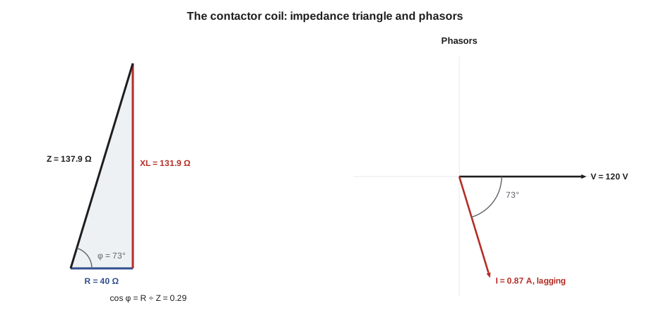
Resistance and reactance do not add directly, because the voltage across a resistance is in phase with the current while the voltage across a reactance is a quarter-cycle, 90°, ahead (for a coil) or behind (for a capacitor). They add as the sides of a right triangle, the impedance triangle:
The angle φ is the phase angle between voltage and current, and cos φ is the power factor. Only the resistance takes real power, P = I²R; the reactance takes reactive power, Q = I²X, and the supply delivers the apparent power S = VI. When X_L equals X_C the reactances cancel, the circuit is at resonance, and the current is limited only by resistance, which is why capacitor banks are designed so that they do not resonate with the system's inductance at a harmonic frequency.
Worked problem
A contactor coil
A contactor coil on 120 V, 60 Hz has a resistance of 40 Ω and an inductance of 0.35 H. Find its reactance, impedance, current, power factor and real power.
Show solution
- Reactance:
- \[X_L = 2\pi \times 60 \times 0.35 = 131.9 \text{ Ω}\]
- Impedance:
- \[Z = \sqrt{40^2 + 131.9^2} = 137.9 \text{ Ω}\]
- Current and power factor:
- \[I = \frac{120}{137.9} = 0.870 \text{ A}, \qquad \cos\varphi = \frac{40}{137.9} = 0.290\]
- Real power:
- \[P = I^2 R = 0.870^2 \times 40 = 30.3 \text{ W}\]
Answer: The coil draws 104 VA but uses only 30 W. If its armature sticks open, the coil's inductance falls because the magnetic circuit has a large air gap, the current rises several times, and the coil overheats; that is why a humming, sticking contactor soon burns out its coil.
Three-phase connections
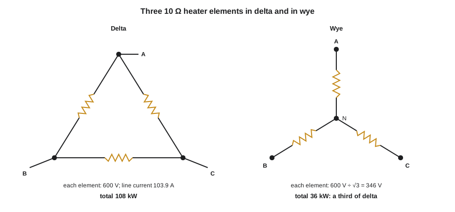
Three-phase loads and windings are connected in wye (star) or delta. In a wye connection each element sits between a line and the neutral point; the line current flows through it, and the voltage across it is the line voltage divided by √3. In a delta connection each element sits between two lines; it has the full line voltage across it, and the line current is √3 times the element's current. In both cases, for a balanced load, the total power is:
Reconnecting a set of elements from delta to wye puts 1/√3 of the voltage across each, so each takes a third of the power, and the total power falls to a third. The same fact is the basis of the old wye-delta motor starter, which starts a delta-wound motor in wye to cut its starting current and torque to a third.
Worked problem
A heater bank in delta and in wye
Three 10 Ω resistive heater elements are connected in delta to a 600 V three-phase supply. Find the element current, the line current and the total power. Then find the power if the same elements are reconnected in wye.
Show solution
- Delta: each element has 600 V across it.
- \[I_{ph} = \frac{600}{10} = 60 \text{ A}, \quad I_L = \sqrt{3} \times 60 = 103.9 \text{ A}, \quad P = 3 \times \frac{600^2}{10} = 108 \text{ kW}\]
- Wye: each element has 600 ÷ √3 = 346.4 V across it.
- \[P = 3 \times \frac{346.4^2}{10} = 36 \text{ kW}\]
Answer: 108 kW in delta and 36 kW in wye: exactly a third. Check: √3 × 600 × 103.9 × 1.0 = 108 kW.
Voltage drop in a feeder
Current flowing through a feeder's resistance and reactance drops part of the supply voltage before it reaches the load. For a balanced three-phase feeder of length L, with resistance R and reactance X per unit length, the line-to-line voltage drop is approximately:
The reactance term matters for large conductors, whose reactance can exceed their resistance, and for low power factor currents such as motor starting. Electrical codes and good practice keep running voltage drop on feeders and branch circuits to a few in 100 of the supply voltage; motors run hotter, slip more and lose torque on low voltage, and a large dip during starting can drop out contactors elsewhere on the same bus.
Worked problem
Voltage drop on the FD fan feeder
The motor draws 54 A at 0.87 power factor. The #4 AWG copper feeder is 75 m long, with R = 0.815 Ω/km at 20 °C and X = 0.16 Ω/km (a typical value for this size in steel conduit). Find the running voltage drop with the conductors at 75 °C, then the dip during starting, when the soft starter limits current to three times full-load current at about 0.35 power factor.
Show solution
- Hot resistance:
- \[R_{75} = 0.815 \times 1.216 = 0.991 \text{ Ω/km}\]
- Running, with sin φ = 0.493:
- \[V_d = \sqrt{3} \times 54 \times (0.991 \times 0.87 + 0.16 \times 0.493) \times 0.075 = 6.6 \text{ V}\]
- As a fraction of 600 V:
- \[\frac{6.6}{600} = 0.011\]
- Starting, at 162 A and sin φ = 0.937:
- \[V_d = \sqrt{3} \times 162 \times (0.991 \times 0.35 + 0.16 \times 0.937) \times 0.075 = 10.5 \text{ V}\]
Answer: A running drop of about 1.1 in 100 and a starting dip in the feeder of about 1.7 in 100, both comfortable. Across the line, at six times full-load current, the starting dip in the feeder alone would have been about 21 V, before counting the dip in the transformer and the bus.
The feeder's copper loss, 3I²R, is also worth knowing: at 54 A with 0.0744 Ω per conductor it is about 650 W, a small but continuous cost, and the reason feeders for motors that run all year are sometimes upsized beyond the minimum.
Transformers
An ideal transformer changes voltage in the ratio of its turns and current in the inverse ratio, so that the power in equals the power out:
A 500 VA control transformer stepping 600 V down to 120 V has a turns ratio of 5:1. At full load its secondary carries 500 ÷ 120 = 4.17 A and its primary 500 ÷ 600 = 0.83 A. Real transformers lose a little power in their windings (copper loss, which rises with the square of the load) and in their cores (iron loss, roughly constant whenever they are energized); large power transformers reach efficiencies above 0.98.
Motor efficiency and energy cost
A motor's efficiency is its shaft output divided by its electrical input. Losses in the windings, the core, the bearings and the cooling fan all turn into heat. Premium efficiency motors cut those losses with more copper, better steel and closer tolerances, and over a motor's life the electricity it uses costs many times its purchase price, so a few points of efficiency matter.
Worked problem
What the new motor saves
The old FD fan motor had an efficiency of 0.920 and the new one 0.945. The fan runs about 6,000 hours a year at an average of 75 in 100 of the motor's 45 kW rating. With electricity at 12 cents per kWh, estimate the yearly saving.
Show solution
- Average output:
- \[0.75 \times 45 = 33.75 \text{ kW}\]
- Energy saved:
- \[33.75 \times 6{,}000 \times \left(\frac{1}{0.920} - \frac{1}{0.945}\right) = 5{,}820 \text{ kWh}\]
- Cost saved:
- \[5{,}820 \times 0.12 \approx 700 \text{ dollars a year}\]
Answer: A modest saving each year, but repeated for twenty years or more of service. The calculation uses the difference of the reciprocals of efficiency, not the difference of efficiencies, because input power is output divided by efficiency.
Ruaridh's check
Ruaridh read Okonkwo's page and changed one figure: he had first used the 20 °C resistance, and the 75 °C value raised the running drop from 5.5 V to 6.6 V. "Always the hot resistance," Ruaridh said, "because that's how the cable is when you need it." He filed the calculation in the motor's folder with the nameplate data and the soft starter settings, and noted the measured voltage at the motor terminals during the first full-load run, 591 V against 600 V at the MCC, a difference of 9 V that included the starter's own small drop.
Common mistakes
MistakeAdding resistance and reactance directly.
InsteadCombine them as the sides of a right triangle: Z = √(R² + X²).
MistakeUsing the 20 °C conductor resistance for a voltage drop at full load.
InsteadCorrect to operating temperature; copper at 75 °C has about 1.22 times its 20 °C resistance.
MistakeThinking a delta-connected load and a wye-connected load of the same elements take the same power.
InsteadIn wye each element sees 1/√3 of the line voltage and the power falls to a third.
MistakeSubtracting efficiencies to find energy saved.
InsteadInput = output ÷ efficiency; subtract the inputs, using the reciprocals of the efficiencies.
MistakeIgnoring reactance in the voltage drop of a starting motor.
InsteadAt low power factor the X sin φ term dominates; include it.
Summary and key terms
- R = ρL ÷ A, and resistance rises with temperature by about 0.393 in 100 per kelvin for copper.
- Series resistances add; parallel reciprocals add; Kirchhoff's current and voltage laws solve any circuit.
- X_L = 2πfL and X_C = 1 ÷ 2πfC; impedance and power factor come from the impedance triangle.
- Three-phase power is √3 V_L I_L cos φ; wye elements see V_L ÷ √3, delta elements carry I_L ÷ √3.
- Feeder voltage drop is about √3 I (R cos φ + X sin φ) L; keep it to a few in 100.
- Transformers change voltage by the turns ratio; motor savings use the reciprocals of efficiency.
- Resistivity
- The resistance of a material per unit length and unit area, a property of the material.
- Kirchhoff's laws
- The current law (currents into a junction equal currents out) and the voltage law (rises equal drops around any loop).
- Inductive reactance
- The opposition of an inductance to alternating current, 2πfL ohms.
- Capacitive reactance
- The opposition of a capacitance to alternating current, 1 ÷ 2πfC ohms.
- Impedance
- The combined opposition of resistance and reactance to alternating current.
- Wye connection
- A three-phase connection with each element between a line and a common neutral point.
- Delta connection
- A three-phase connection with each element between two lines.
- Voltage drop
- The voltage lost along a conductor because of its resistance and reactance.
Practice problems
Work each problem on paper first, then reveal the answer to check.
Find the resistance of 200 m of copper conductor with an area of 10 mm² at 20 °C.
Show answer
1.724 × 10⁻⁸ × 200 ÷ 10 × 10⁻⁶ = 0.345 Ω.
Three resistors of 6, 12 and 4 Ω are in parallel. Find their combined resistance.
Show answer
1/R = 1/6 + 1/12 + 1/4 = 0.5; R = 2 Ω.
A coil of 0.2 H and 50 Ω is on 120 V, 60 Hz. Find its current.
Show answer
X_L = 75.4 Ω; Z = 90.5 Ω; I = 1.33 A.
A balanced 600 V wye load takes 20 A per line at unity power factor. Find the power.
Show answer
√3 × 600 × 20 = 20.8 kW.
Lesson quiz · 5 questions
Score 60% or more to complete this lesson.
Create a free account to save your progress, take quizzes and earn a certificate.