
PLB-330 · Lesson 3 of 12 · 20 min
Controlled-flow and siphonic roof drainage
The roof of the Ridgeview east wing is enormous: a low, wide building with almost an acre of flat roof over the diagnostic imaging department and the main entrance. The mechanical drawings showed only eight roof drains for the whole area and very few vertical leaders, with long horizontal pipes running almost level just below the roof deck. Maya assumed it was a mistake. "That's a siphonic system," Luis said. "It's designed to run full, and when it does, it pulls water off the roof much faster than an ordinary drain. You'll also see controlled-flow drains on the north block, which do the opposite: they hold water on the roof on purpose." This lesson covers both: roof drainage that slows water down to protect the sewer, and roof drainage that speeds it up to save piping.
Two ideas that look opposite
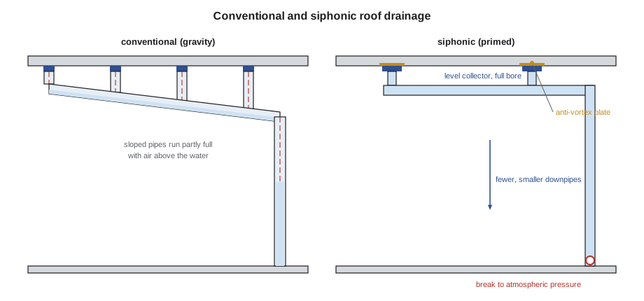
Conventional roof drainage, covered in lesson 2, works by gravity with the pipes partly full. Water enters the drain, falls through the leader with air, and flows along horizontal drains at a slope. Two specialty approaches change this. Controlled-flow roof drainage deliberately restricts how fast water can leave the roof, using the roof itself as a temporary storage tank during a storm. Siphonic roof drainage does the opposite: it designs the piping to run completely full of water, so that the drop in height from roof to ground creates suction that pulls water through the system at high velocity. One protects the city sewer and saves on site storage; the other reduces the number and size of pipes inside the building. Both depend on careful engineering, and neither can be modified on site without the designer's approval.
Controlled-flow roof drains
A controlled-flow roof drain has a weir or a set of slots inside its dome that limits the flow into the leader for any given depth of water. At the start of a storm, water passes through freely. As the storm intensifies and rain falls faster than the weir allows, water collects on the roof, rising to a design depth before the storm passes. Afterward, the stored water drains away slowly over the next few hours. The peak flow sent to the building storm drain and the city sewer is much lower than it would be with conventional drains, and the site may need a smaller underground storage tank, or none.
The design limits are set by the structure. The roof must carry the weight of the stored water, so the engineer chooses a maximum ponding depth, often 100 to 150 mm, and the structural engineer designs the deck for that load plus snow. The roof must also drain completely within a set time after the storm, commonly 24 hours, so that it is not still loaded when the next storm or a heavy snow arrives. Overflow scuppers or overflow drains are set at the maximum ponding depth so that water can never rise higher, even if the controlled drains clog.
Controlled-flow systems need a roof that is truly flat or gently sloped to the drains, with the membrane and flashings carried high enough up every parapet, curb and penetration to stay above the maximum water level. They also need maintenance. A controlled-flow drain with a blocked weir does not just drain slowly; it stores water longer than designed. Building operators are given a maintenance schedule, and roof hatches often carry a sign explaining that water on the roof during a storm is normal.
Worked problem
How much water does a controlled-flow roof hold?
The north block of the Ridgeview wing has 2,400 m² of roof with controlled-flow drains and a design maximum ponding depth of 75 mm averaged over the roof. How much water can the roof store, and what extra load does it place on the deck?
Show solution
- \[V = A \times d = 2400\ \text{m}^2 \times 0.075\ \text{m} = 180\ \text{m}^3\]
- \[w = \rho g d = 1000 \times 9.81 \times 0.075 \approx 736\ \text{N/m}^2 \approx 0.74\ \text{kN/m}^2\]
- That is 180 m³ the site does not need to store underground during the peak of the storm.
Answer: About 180 m³, at about 0.74 kN/m², which the structural engineer adds to the roof design load.
How siphonic drainage works
A siphonic system starts as an ordinary gravity system. In light rain, water flows into specially designed drains and runs partly full, just like a conventional system. As the rain increases, the water level over each drain rises, and a baffle or anti-vortex plate in the drain stops air from being drawn in with the water. Once the pipes fill completely, the system primes: the whole column of water from the roof drains down to the point of discharge acts as one, and the weight of the falling water in the vertical pipe creates negative pressure in the horizontal collector pipes near the roof. Water is then sucked through the system at velocities of several metres per second, far faster than in a gravity drain of the same size.
The driving force is the height difference between the roof drains and the point where the system breaks back to atmospheric pressure, usually at a manhole or a gravity drain near the ground. A building 10 m tall gives roughly 10 m of head, or about 98 kPa, to overcome friction and accelerate the water. Because that energy is available, the horizontal collector pipes can be laid level, without the slope a gravity drain needs, and they can be much smaller. One horizontal collector can serve many drains spread across a large roof, connecting to just one or two vertical downpipes.
Designing and building a siphonic system
Siphonic systems are designed with hydraulic software, usually by the drain manufacturer or a specialist, because every pipe size and length affects the balance between drains. The design must make sure that each drain carries its share of the flow, that the negative pressure never falls low enough to damage pipes or cause cavitation, and that the system primes reliably in a design storm and still drains safely as a gravity system in light rain. The calculation is iterative: change one pipe and the pressures throughout the system change.
This has three practical consequences for plumbers. First, the installation must match the design exactly. A pipe one size larger than drawn, an extra fitting, or a horizontal run a few metres longer can stop the system from priming or unbalance the flow between drains. Any change must go back to the designer for recalculation. Second, the pipe and fittings must be rated for negative pressure. Many siphonic systems use high-density polyethylene welded by butt fusion or electrofusion, or cast iron and steel with restrained joints, because ordinary drainage joints may pull apart or collapse under suction. Third, supports must be designed for the dynamic forces of water moving at high velocity and for thermal movement, often with a rail system clamped to the structure.
Siphonic systems still need overflow protection. Because they are designed for a specific storm, a heavier storm or a blocked drain can overwhelm them. Overflow drains or scuppers, piped separately to discharge where they can be seen, are required just as with conventional systems.
# Siphonic system: how much head is available and what velocity can it support? (practice estimate)
import math
G = 9.81

def available_head_m(roof_elev, discharge_elev):
    return roof_elev - discharge_elev

def velocity_for_losses(head_m, k_total):
    """All head is lost to friction and fittings: h = K v^2 / 2g -> v = sqrt(2 g h / K)."""
    return math.sqrt(2 * G * head_m / k_total)

h = available_head_m(roof_elev=11.2, discharge_elev=0.5)
print(f"available head: {h:.1f} m = {h * 9.81:.0f} kPa")
for k in (20, 30, 45):
    v = velocity_for_losses(h, k)
print(f"total loss coefficient {k:2d}: velocity about {v:.1f} m/s")available head: 10.7 m = 105 kPa total loss coefficient 20: velocity about 3.2 m/s total loss coefficient 30: velocity about 2.6 m/s total loss coefficient 45: velocity about 2.2 m/s
The script is a simplification, but it shows the idea. All of the available head is used up by friction and fitting losses once the system is running full. A system with fewer losses runs faster and carries more water. Real design software adds pipe friction for each length and size, checks the pressure at every node, and confirms that no point drops below the limit the pipe can tolerate.
Comparing the approaches
| Feature | Conventional gravity | Controlled-flow | Siphonic |
|---|---|---|---|
| Pipes run | Partly full | Partly full | Full when primed |
| Horizontal slope | Required | Required | None needed |
| Number of downpipes | Many | Many | Few |
| Peak flow to sewer | High | Reduced on purpose | High |
| Water stored on roof | No | Yes, to a design depth | No |
| Design method | Code tables | Code tables and structural check | Hydraulic software |
| Changes on site | Within code rules | With structural approval | Only with recalculation |
On the Ridgeview wing the engineer used both. The south roof over imaging, with its long spans and an open ceiling space below full of ductwork, used siphonic drainage so that only two downpipes had to pass through the floors. The north block, where the site had little room for an underground tank, used controlled-flow drains to hold water on the roof during storms and meet the city's release rate.
Installing and commissioning specialty roof drains
Whichever system is used, the drains themselves come as engineered parts. Controlled-flow drains are supplied with a specific weir for each location, and the weir openings must not be enlarged or removed. Siphonic drains include the anti-vortex baffle, which must be installed and kept in place. Both kinds are flashed into the membrane with the roofing contractor, and the plumber and roofer must coordinate the sequence so that the drain is clamped correctly and the membrane is not damaged.
Testing a siphonic system follows the manufacturer's procedure, often a water test of the full system plus a pressure or leak test of the welded pipe. Some projects flood a section of roof to watch the system prime. Records include the as-built pipe lengths, which the designer checks against the design model. For controlled-flow systems, the inspector checks the weir type at each drain, the overflow heights and the membrane flashing heights.
Maintenance is part of commissioning. The owner's staff are shown how to inspect domes and strainers, clear debris after storms and in autumn, and recognize the signs of a problem: water that stays on a controlled-flow roof long after the rain stops, or noisy, gurgling siphonic drains that suggest air is being drawn in because a baffle is missing.
Installing and commissioning siphonic systems
Siphonic systems are less forgiving than gravity systems, so their installation follows the designer's drawings exactly. Pipe sizes, lengths, fittings and elevations are all part of the hydraulic calculation, and a change of one size or an extra fitting can stop the system priming or create excessive negative pressure. Horizontal collector pipes are usually installed level rather than sloped, because the system runs full bore once primed, and they are hung from supports designed to resist the forces created when the system primes and breaks. Expansion and the thrust at changes of direction are taken by fixed points and sliding brackets set out by the designer.
Any field change goes back to the designer for a new calculation before it is installed. After installation, the system is tested for tightness and inspected against the drawings, and the designer or the system supplier usually signs off that it matches the design. Roof drains with flow control or siphonic baffles must not be replaced with ordinary drains during reroofing, because the whole roof's drainage depends on their performance. Maya added a note to the Ridgeview operation manual so that the next roofing contractor would know which drains were part of the engineered system.
Common mistakes
MistakeEnlarging a controlled-flow weir because the roof drains slowly.
InsteadSlow drainage is the design; changing the weir defeats storm water control and may break the approval.
MistakeAdding an extra fitting or changing a pipe size in a siphonic system.
InsteadEvery change needs the designer's recalculation, or the system may not prime or may unbalance.
MistakeUsing ordinary drainage joints in siphonic pipework.
InsteadUse pipe and joints rated for the negative pressures the design predicts.
MistakeLeaving out overflow drains on a specialty system.
InsteadEvery roof that can trap water needs independent overflow protection.
Summary and key terms
- Controlled-flow roof drains restrict outflow and store water on the roof during storms to reduce peak flows to the sewer.
- Ponding depth and drain-down time are limited by the roof structure; overflows are set at the maximum depth.
- Siphonic systems prime and run full, using the building's height to drive high velocities through level, smaller pipes.
- Siphonic systems are designed with hydraulic software and must be installed exactly as designed.
- Both systems need independent overflow protection and regular maintenance.
- Weirs and anti-vortex baffles are engineered parts that must not be altered.
- Controlled-flow roof drain
- A roof drain with a weir that limits outflow, storing water on the roof during a storm.
- Siphonic roof drainage
- A roof drainage system designed to run full so that falling water creates suction and high velocity.
- Priming
- The point at which a siphonic system fills completely and begins to flow as a full siphon.
- Anti-vortex baffle
- A plate in a siphonic drain that stops air being drawn in with the water.
- Drain-down time
- The time a controlled-flow roof takes to empty after a storm.
Practice problems
Work each problem on paper first, then reveal the answer to check.
A 1,500 m² roof stores water to an average of 50 mm. How much water is stored?
Show answer
1,500 × 0.05 = 75 m³.
Why can siphonic collector pipes be laid level?
Show answer
The height of the building provides the energy to move the water once the system runs full.
What happens if a siphonic drain's baffle is left out?
Show answer
Air is drawn in, the system may not prime, and it may run noisily and carry less water.
Why are overflows still needed with controlled-flow drains?
Show answer
Blocked weirs or extreme storms could raise the water above the design depth and overload the roof.
A siphonic system has 9 m of head. About how much pressure is that?
Show answer
9 × 9.81 ≈ 88 kPa.
Lesson quiz · 5 questions
Score 60% or more to complete this lesson.
Create a free account to save your progress, take quizzes and earn a certificate.