
PLB-330 · Lesson 11 of 12 · 21 min
Fire service connections and backflow protection
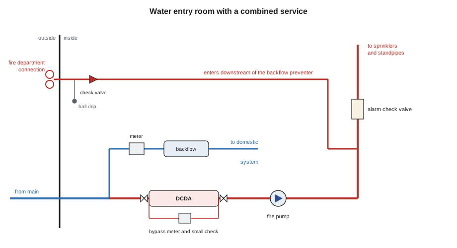
At Kingsway Tower, the fire protection contractor's crew had installed the sprinkler system and standpipes through every floor, but the water reached them through pipe Maya's crew had laid. The 200 mm water service entered the basement through a wall sleeve and split in a room the drawings called the water entry room: one branch to the domestic water meter and booster pumps, the other to the fire service, with its own double check detector assembly, a fire pump and the riser that fed the sprinklers and standpipes. On the street wall outside, a fire department connection with two inlets let firefighters pump water into the system. "Fire and plumbing meet in this room," Luis said. "Who installs what depends on the province and the contract, but everyone needs to understand the whole picture, because a mistake here can poison the city's water or leave a building without fire protection."
Who does what
Fire protection is a separate trade in many jurisdictions. In Ontario, sprinkler and fire protection installer is its own compulsory trade, and the sprinkler system downstream of the fire service connection is installed by that trade. Plumbers commonly install the water service up to a defined point, and often the backflow preventer on the fire line, depending on local rules and the contract. Some backflow preventers on fire lines must be tested by a certified tester, who may be from either trade. Because the line between the trades varies, the contract documents and local rules decide, and both trades must coordinate where their work meets.
The standards for fire protection water supplies are mostly published by NFPA, and they are adopted in both Canada and the United States through building and fire codes. NFPA 13 covers sprinkler system installation, NFPA 14 covers standpipe and hose systems, NFPA 24 covers private fire service mains and their appurtenances, and NFPA 25 covers inspection, testing and maintenance of water-based fire protection systems. Backflow protection on fire lines is governed by the plumbing code, the water utility's cross-connection control program and CSA B64.10, which covers selection and installation of backflow preventers, with CSA B64.10.1 covering their maintenance and field testing.
The fire service and the domestic service
Large buildings usually have a fire service separate from the domestic service, either as a separate pipe from the main or as a branch from a combined service inside the building. Separation matters for three reasons. First, the fire service is sized for the very large flows of a sprinkler or standpipe system in a fire, which may be ten or twenty times the domestic peak. Second, water in a fire line sits still for months or years and loses its quality, so it must never mix back into the drinking water. Third, the utility may want to meter or monitor the fire line separately to detect unauthorized use.
A combined service, where one pipe from the main feeds both the domestic system and the fire system, is common on smaller commercial buildings and on some high-rise residential buildings. The split happens inside the building, with the fire branch taken off upstream of the domestic meter or through a meter sized for fire flow, as the utility requires. The fire branch then passes through its own backflow preventer. Combined services must be sized for the fire flow plus a share of the domestic demand, and the domestic backflow preventer is arranged so that a fire flow does not starve the domestic system or vice versa.
Why fire lines need backflow protection
A sprinkler system is a cross-connection waiting to happen. The water in it is stagnant, often discoloured and high in iron and bacteria. Some systems contain antifreeze, corrosion inhibitors or foam concentrate. The fire department connection allows firefighters to pump water into the system from any source, including a pond or a river, and from pumper trucks that may have been used with non-potable water. If pressure in the city main dropped, for example during a main break or heavy hydrant use nearby, water from the fire system could flow back into the public supply.
Backflow preventers on fire lines stop that. The type required depends on the hazard the fire system presents. The usual pattern is:
- A double check valve assembly, or a double check detector assembly where the utility wants to detect leaks or unauthorized use, for systems that contain only potable water with no chemicals, the most common case. These are treated as minor or moderate hazards.
- A reduced pressure principle assembly, or a reduced pressure detector assembly, for systems with antifreeze, corrosion inhibitors, foam or other additives, or where the fire department connection can draw water from a non-potable source. These are treated as severe or high hazards.
- Additional or different protection where the local cross-connection program requires it, which can vary between utilities.
A detector assembly includes a small bypass line with its own small backflow preventer and a meter. Small flows, such as a slow leak in the fire system or water drawn illegally from a test connection, pass through the bypass and register on the meter, while a fire flow opens the main check valves and passes through the full-size assembly. Utilities read these meters to find leaks and theft.
The fire department connection
The fire department connection, sometimes called a siamese for its two-inlet shape, lets firefighters boost pressure and flow in the sprinkler or standpipe system using a pumper truck. It is piped into the system downstream of the backflow preventer and the system control valve, so that water pumped in goes to the sprinklers and standpipes and cannot reach the city main. A check valve in the connection piping prevents system water from flowing out through the connection, and an automatic drain or ball drip empties the piping between the check valve and the inlets so it does not freeze.
Location and identification are set by the fire code and the local fire department. The connection must be visible and accessible from the street, near a hydrant, and clearly signed with the system it serves. In buildings with more than one system, each connection is labelled, for example as sprinkler, standpipe or combined. Caps on the inlets keep out debris, and many fire departments require locking caps. Plumbers are not usually responsible for the connection itself, but they must not block it with their own work, and they may be responsible for the drain from its ball drip.
Water supply testing and the hydraulic picture
A sprinkler system is designed hydraulically: the designer calculates the flow and pressure needed at the most demanding group of sprinklers and works back to the point of supply. To know whether the city main can supply it, the designer uses a hydrant flow test. One hydrant is fitted with a gauge to read static pressure, with no flow, and residual pressure while water flows from a nearby hydrant. The flowing hydrant's discharge is measured with a pitot gauge. The test gives three numbers: static pressure, residual pressure and the flow at that residual pressure. Water supply curves plot these on special graph paper scaled to flow raised to the power 1.85, because pressure loss in pipes varies roughly with that power of flow.
At Kingsway, the hydrant test on the street gave a static pressure of 520 kPa and a residual of 380 kPa at a flow of 95 L/s. The designer needed to know how much flow the main could deliver at 140 kPa residual, the minimum the utility allowed, and what pressure would be available at the sprinkler system's demand flow.
Worked problem
Flow available from a hydrant test
Static 520 kPa, residual 380 kPa at 95 L/s. Find the flow available at 140 kPa residual.
Show solution
- Pressure drop varies with flow to the power 1.85, so flow varies with the drop to the power 0.54.
- \[Q_r = Q_f \times (\frac{p_s - p_r}{p_s - p_f})^{0.54}\]
- \[Q_r = 95 \times (\frac{520 - 140}{520 - 380})^{0.54} = 95 \times (2.714)^{0.54}\]
- \[Q_r \approx 95 \times 1.714 \approx 163\ \text{L/s}\]
Answer: About 163 L/s is available at 140 kPa residual. This sets the upper limit of what the main can deliver to the building.
# Water supply from a hydrant flow test: available pressure at a demand flow
def pressure_at(q, ps, pr, qf):
    """Pressure available at flow q from a test with static ps, residual pr at flow qf (kPa, L/s)."""
    return ps - (ps - pr) * (q / qf) ** 1.85

PS, PR, QF = 520, 380, 95            # Kingsway hydrant test
LOSSES = {"service and meter": 25, "DCDA backflow preventer": 55, "elevation to riser base": 15}

for demand in (25, 40, 60):          # sprinkler demand plus hose allowance, L/s
    p = pressure_at(demand, PS, PR, QF)
    net = p - sum(LOSSES.values())
    print(f"demand {demand:3d} L/s: main {p:5.0f} kPa, after losses {net:5.0f} kPa")
print("losses:", ", ".join(f"{k} {v} kPa" for k, v in LOSSES.items()))demand 25 L/s: main 508 kPa, after losses 413 kPa demand 40 L/s: main 492 kPa, after losses 397 kPa demand 60 L/s: main 460 kPa, after losses 365 kPa losses: service and meter 25 kPa, DCDA backflow preventer 55 kPa, elevation to riser base 15 kPa
The script shows why the backflow preventer matters to the fire designer. A double check detector assembly can lose a significant part of the available pressure at high flow, and a reduced pressure assembly usually loses more. Choosing the assembly, its size and its friction loss curve is part of the hydraulic design, and substituting a different model in the field without approval can leave the sprinklers short of pressure. Where the available pressure is not enough for the tower's upper floors, a fire pump boosts it, as at Kingsway.
Installing backflow preventers on fire lines
Fire line backflow preventers are large, heavy assemblies with resilient-seated gate or butterfly shut-off valves at each end, test cocks and, for detector types, a bypass meter. They are installed where they can be tested and maintained: usually indoors in a heated room or in an approved enclosure, with clearance around them for testing and repair, and at a height the standard and the utility accept. Reduced pressure assemblies discharge water from their relief valve when they sense a problem, so they need a floor drain or air-gapped drain sized for the full relief discharge, which can be large. They must not be installed in pits where the relief port could be submerged. The shut-off valves on fire lines must be supervised, usually with tamper switches connected to the fire alarm system, so that a closed valve is reported.
Before installation, the line is flushed to remove debris that could foul the check valves. After installation, the assembly is tested by a certified tester before the system is put in service, and the test report goes to the utility. The fire line is also flushed and hydrostatically tested under NFPA requirements, typically by the fire protection contractor, before the sprinkler system is accepted.
Inspection, testing and the forward flow test
Backflow preventers on fire lines are tested at least once a year, as the utility's cross-connection program requires, by a certified tester using a differential pressure test kit. NFPA 25 also requires a forward flow test of the backflow preventer at least once a year, which proves that the assembly can pass the system's design flow, not just that its checks hold tight. Many buildings install a test header downstream of the assembly for this purpose, with hose connections that let the full flow be discharged safely. Without a forward flow test, a check valve could be stuck partly closed and nobody would know until the sprinklers needed water.
The plumber's link to PLB-320 is direct: the backflow testing and cross-connection control skills from that course apply here at a larger scale. The main differences are the size and weight of the assemblies, the need to coordinate shutdowns with the fire alarm monitoring company and the fire department, and the impairment procedures that apply whenever fire protection is out of service. When a fire line is shut down for testing or repair, the owner must notify the fire department and the monitoring company, and may need a fire watch until the system is restored.
Common mistakes
MistakeConnecting the fire department connection upstream of the backflow preventer.
InsteadIt must enter downstream so pumped water cannot reach the city main.
MistakeUsing a double check assembly on a system that contains antifreeze.
InsteadSystems with additives need a reduced pressure assembly or the protection the program specifies.
MistakeSubstituting a different backflow preventer model on a fire line in the field.
InsteadIts friction loss is part of the hydraulic design; changes need approval.
MistakeShutting down a fire line without notifying anyone.
InsteadFollow the impairment procedure: notify the fire department and monitoring company, and arrange a fire watch if needed.
Summary and key terms
- Fire protection is often a separate trade; contracts and local rules set where plumbing work ends.
- Fire services are separated from domestic services or split from a combined service with separate backflow protection.
- Double check or double check detector assemblies protect potable-water systems; reduced pressure types protect systems with additives or non-potable sources.
- The fire department connection enters downstream of the backflow preventer, with a check valve and ball drip.
- Hydrant flow tests define the supply curve; backflow preventer losses are part of the hydraulic design.
- Fire line backflow preventers are tested annually and forward flow tested under NFPA 25.
- Detector assembly
- A backflow preventer with a metered bypass that registers small flows such as leaks or theft.
- Fire department connection
- An exterior inlet that lets firefighters pump water into a sprinkler or standpipe system.
- Residual pressure
- The pressure remaining in a main while water flows from a nearby hydrant.
- Forward flow test
- A test proving a backflow preventer can pass the fire system design flow.
- Impairment
- A period when a fire protection system is out of service, requiring notification and precautions.
Practice problems
Work each problem on paper first, then reveal the answer to check.
Why does the fire department connection enter downstream of the backflow preventer?
Show answer
So water pumped in from any source cannot flow back to the public main.
When is a reduced pressure assembly used on a fire line?
Show answer
When the system contains antifreeze or other additives, or can draw from a non-potable source.
Static 480 kPa, residual 350 kPa at 80 L/s. What is the pressure at 40 L/s?
Show answer
480 − 130 × 0.5^1.85 ≈ 480 − 36 = 444 kPa.
What does the bypass meter on a detector assembly reveal?
Show answer
Small flows such as leaks or unauthorized use.
What must happen before a fire line is shut down?
Show answer
The fire department and monitoring company are notified under the impairment procedure.
Lesson quiz · 5 questions
Score 60% or more to complete this lesson.
Create a free account to save your progress, take quizzes and earn a certificate.