
PLB-330 · Lesson 10 of 12 · 21 min
Medical gas systems II: installation, brazing, testing and certification
By the time the Ridgeview east wing's walls were framed, the medical gas crew had more paperwork than pipe. Every brazer's qualification card was on file with the general contractor. Daniela kept a log of every joint, by drawing location and brazer. Nitrogen cylinders lined the corridor, each with a regulator and flowmeter set up for purging. "Installing the pipe is maybe half the job," Daniela told Maya. "The other half is proving it's clean, tight, connected to the right outlets and carrying the right gas. We test it, then someone independent tests it again, and nobody connects it to the hospital until both are signed." This lesson covers how medical gas pipelines are installed and brazed, the sequence of tests that proves them, and the certification that stands behind every step.
Before the first joint
Medical gas work begins with qualified people and qualified procedures. The installing contractor must have certified installers for the work and brazers who have passed a brazing performance qualification using a written brazing procedure specification, typically under ASME Boiler and Pressure Vessel Code Section IX or AWS B2.2. Many owners also require the contractor to show proof of training for everyone on the crew, and the CSA Group certification program sets the expectations for installer knowledge in Canada. Before work starts, the contractor reviews the drawings with the engineer, confirms the materials on site are cleaned for oxygen service and properly marked, and sets up storage that keeps tube and fittings capped, clean and dry.
Each brazer's qualification covers a specific procedure, position and range of sizes. If the procedure changes, for example to a different filler metal or joint design, or if the brazer has not used the procedure within the period the standard allows, the brazer must requalify. Daniela kept a matrix on the site office wall that showed which brazer was qualified for which work and when each qualification would lapse.
Installation practices
Medical gas pipe is handled like a clean instrument. Tubes stay capped until they are cut. Cutting is done with a clean tube cutter or saw that does not leave oil or chips inside, and the burr is removed with a clean deburring tool while holding the tube so chips fall out, not in. Fittings are kept in their bags until they are used. Joints are cleaned with clean, oil-free abrasive pads, never with steel wool or anything that leaves a residue. Gloves or clean hands are used when handling surfaces that will be inside the pipe. Any tube or fitting that becomes contaminated is set aside and either recleaned by an approved method or discarded.
Pipe is supported at the intervals the standard requires, which are closer for small tubes than for large ones, and is kept separate from electrical conduit and other piping. Where medical gas piping passes through walls and floors, it is sleeved or protected and the penetration is firestopped with a listed system. Pipelines are labelled with the gas name and flow direction at intervals of no more than about 6 m, at every change of direction and on both sides of walls and floors, so anyone working in the ceiling can identify them.
Zone valve boxes, outlets and alarm sensors are installed as rough-in assemblies, with their own protection so that drywall dust and paint do not enter them. Outlets are usually installed in two stages: a rough-in body that is brazed to the pipeline and tested with the piping, and a finish assembly that is installed after walls are finished and before final testing. Each outlet rough-in is gas-specific, so that, for example, an oxygen finish assembly cannot be installed in a medical air rough-in.
Brazing under a nitrogen purge
Medical gas joints are brazed with copper-phosphorus filler metal, often called BCuP, on copper-to-copper joints. This filler metal flows without flux on copper because the phosphorus acts as a deoxidizer. Flux is used only where the standard allows it, typically for joints between copper and brass or bronze components using a silver-based filler, and any flux residue must be thoroughly removed afterward, because flux left inside the pipe can contaminate the gas.
The critical difference from ordinary brazing is the internal purge. While a joint is heated, oil-free dry nitrogen flows gently through the pipe. Without it, the hot inside surface of the copper reacts with the oxygen in the air and forms a black copper oxide scale. That scale later breaks off, travels downstream and can lodge in patient equipment such as flowmeters, regulators and ventilator valves. With a continuous nitrogen purge, the inside of a brazed joint stays bright and clean.
The purge is set up with a regulator and a flowmeter on the nitrogen cylinder, connected to the section being brazed, with the far end open or fitted with a small vent so the nitrogen keeps moving. The flow is enough to displace the air but not so high that it pressurizes the joint or blows filler metal out. When the joint has cooled, the purge is continued briefly and then stopped. Only the nitrogen grade required by the standard is used; ordinary industrial nitrogen with unknown moisture or oil content is not acceptable.
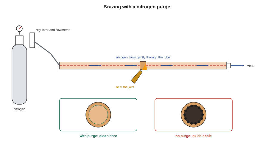
Every completed joint is visually inspected on the outside for full penetration and a continuous fillet, with no cracks, overheating or filler metal left in globules. The standard also requires sample joints to be cut open and inspected, and the brazer's qualification depends on producing joints that pass both a visual check and destructive testing during qualification. On Ridgeview, the inspector randomly selected joints for cutting at the end of each week, and Daniela recorded each one in the joint log.
Installer tests
When a section of pipeline is complete, and before walls and ceilings are closed, the installer carries out a series of tests. The exact names, pressures and durations come from the standard, but the sequence follows the same logic everywhere. First, an initial blowdown with nitrogen clears debris from the pipe. Next, an initial pressure test checks every joint at a pressure above working pressure, with each joint checked for leaks with a leak detection solution that is safe for oxygen service. A cross-connection test then proves that each pipeline is separate from every other one: one pipeline at a time is pressurized while the others are at atmospheric pressure, and every outlet is checked to confirm that gas comes only from the outlets of the pressurized system. A piping purge test blows clean nitrogen through each outlet until no discoloration or particles appear on a clean white cloth. Finally, a standing pressure test holds the system under pressure for 24 hours to prove it does not leak.
The standing pressure test must account for temperature. A sealed pipeline full of nitrogen loses pressure if it cools overnight and gains pressure if it warms, even if nothing leaks. The tester records the temperature at the start and end of the test and corrects the reading. A pressure change explained by temperature is acceptable; any change not explained by temperature means a leak, which must be found, repaired and retested.
# Standing pressure test: correct the final reading for temperature (ideal gas, absolute values)
P_ATM = 101.3  # kPa

def expected_gauge(p_start_gauge, t_start_c, t_end_c):
    p_abs = p_start_gauge + P_ATM
    return p_abs * (t_end_c + 273.15) / (t_start_c + 273.15) - P_ATM

p_start, t_start = 480.0, 21.0     # kPa gauge, deg C at start of the 24 h test
for t_end, p_end in [(18.0, 474.0), (21.0, 471.0), (24.0, 486.0)]:
    exp = expected_gauge(p_start, t_start, t_end)
    diff = p_end - exp
    verdict = "explained by temperature" if abs(diff) <= 2.0 else "unexplained - look for a leak"
print(f"end {t_end:4.1f} C: read {p_end:.0f} kPa, expected {exp:.1f} kPa, difference {diff:+.1f} -> {verdict}")end 18.0 C: read 474 kPa, expected 474.1 kPa, difference -0.1 -> explained by temperature end 21.0 C: read 471 kPa, expected 480.0 kPa, difference -9.0 -> unexplained - look for a leak end 24.0 C: read 486 kPa, expected 485.9 kPa, difference +0.1 -> explained by temperature
The first and third readings match the temperature change within the practice tolerance used here. The second shows a pressure drop with no temperature change, which means a leak somewhere in the section. The real acceptance criteria come from the standard and the specification, but the method is always the same: convert to absolute pressure and absolute temperature, predict the final pressure, and compare.
Worked problem
Temperature correction on a standing test
A section is charged to 480 kPa gauge at 21 °C. The next morning, the temperature is 18 °C. What pressure should the gauge read if nothing has leaked?
Show solution
- Work in absolute pressure and absolute temperature.
- \[p_1 = 480 + 101.3 = 581.3\ \text{kPa abs}, \quad T_1 = 294.15\ \text{K}, \quad T_2 = 291.15\ \text{K}\]
- \[p_2 = p_1 \times \frac{T_2}{T_1} = 581.3 \times \frac{291.15}{294.15} \approx 575.4\ \text{kPa abs}\]
- \[p_{2,g} = 575.4 - 101.3 \approx 474\ \text{kPa gauge}\]
Answer: About 474 kPa. A reading close to this shows no leak; a reading clearly lower means the section must be checked.
Independent verification
After the installer's tests, the system is verified by a qualified person who is independent of the installing contractor, usually hired by the owner. The verifier repeats or witnesses key tests and carries out others that only a verifier performs. These typically include a standing pressure test, a cross-connection test, valve and alarm tests, a piping purge test, a particulate test that draws gas through a filter at each outlet and checks the filter for particles, a purity test that checks each outlet for moisture, hydrocarbons and other contaminants, a final tie-in test after the new system is connected to the existing source, an operational pressure test at the outlets under flow, and a gas concentration test that proves each outlet delivers the right gas. Medical air is also tested for air quality at the source. Only after the verifier issues a written report showing that every test has passed may the system be used for patients.
The concentration test is the last line of defence against a crossed connection. The verifier connects an analyzer to every outlet in turn and confirms the gas. A wrong connection that slipped through every earlier step would show up here as, for example, nitrous oxide at an oxygen outlet. History shows why this matters: deaths have occurred when oxygen and nitrous oxide lines were crossed in hospitals and patients received an anaesthetic gas instead of oxygen. Every test in the sequence exists because something went wrong somewhere before.
Tie-ins to existing systems
Ridgeview's new wing was fed from the existing tower's oxygen, air and vacuum sources, so the new pipelines had to be connected to live systems serving patients. A tie-in like this is planned weeks in advance with the hospital's facilities team, clinical leaders, the verifier and the engineer. The plan identifies which valves will close, which patients and areas will be affected, how long the shutdown will last, and what backup will be used, such as portable cylinders at each bedside in affected areas. Staff are briefed, and the hospital's own authorized staff operate the valves.
The tie-in itself is fast and disciplined. The installer cuts into the existing pipeline, brazes the connection under a nitrogen purge, and checks the joint. The system is then returned to service, and the verifier tests the tie-in joint and the outlets downstream of it for pressure, purity and concentration before patients are reconnected. On Ridgeview, the oxygen tie-in took place at two in the morning and was complete, verified and back in service in under three hours.
Records, maintenance and the people behind the system
A medical gas project ends with a documentation package: brazer qualifications, joint logs, installer test reports, the verifier's report, as-built drawings showing every valve and outlet, and the operation and maintenance manuals for the source equipment and alarms. The hospital uses these records to maintain the system, which must be inspected and tested at regular intervals for its whole life, and the people who maintain it must also be trained for the work. The standard and the health authority set those requirements.
For an apprentice, the path into medical gas work runs through the trade first: a plumber or pipefitter learns brazing, piping and testing, then completes the training and examinations for medical gas installer certification, and qualifies as a brazer under a medical gas brazing procedure. Certification must be kept current through renewal and continued work. Maya's notes from her time on the crew became the start of her study file for certification once she finished her apprenticeship.
Common mistakes
MistakeBrazing without a nitrogen purge because the joint is small.
InsteadEvery joint needs a purge; oxide scale from one joint can damage patient equipment.
MistakeUsing flux on copper-to-copper joints with BCuP filler.
InsteadFlux is used only where allowed, such as on brass or bronze components with silver filler, and must be cleaned off.
MistakeIgnoring temperature when reading a standing pressure test.
InsteadCorrect the reading for temperature using absolute values before deciding whether it passed.
MistakePutting a new system in service after the installer's tests.
InsteadAn independent verifier must test it and issue a report first.
Summary and key terms
- Medical gas work needs certified installers and brazers qualified to a written procedure.
- Tube and fittings stay capped and clean; pipelines are supported, labelled and protected.
- Joints are brazed with BCuP filler under a continuous nitrogen purge to prevent oxide scale.
- Installer tests include blowdown, initial pressure, cross-connection, purge and a 24-hour standing pressure test.
- An independent verifier performs purity, particulate, pressure and concentration tests before the system is used.
- Tie-ins to live systems are planned with the hospital and verified before patients are reconnected.
- BCuP
- Copper-phosphorus brazing filler metal used on copper-to-copper joints without flux.
- Nitrogen purge
- A flow of oil-free dry nitrogen through the pipe during brazing to prevent internal oxidation.
- Cross-connection test
- A test proving that each gas pipeline is connected only to its own outlets.
- Standing pressure test
- A test holding the pipeline under pressure, typically for 24 hours, to prove it does not leak.
- Verifier
- An independent qualified person who tests and certifies a medical gas system before use.
Practice problems
Work each problem on paper first, then reveal the answer to check.
Why is nitrogen flowed through the pipe during brazing?
Show answer
To prevent copper oxide scale forming inside the joint.
A section is charged to 400 kPa gauge at 20 °C. At 25 °C, what should it read with no leak?
Show answer
(400 + 101.3) × 298.15/293.15 − 101.3 ≈ 408.5 kPa.
How does a cross-connection test work?
Show answer
One pipeline is pressurized while others are at atmosphere, and every outlet is checked to see that gas comes only from that pipeline's outlets.
Who performs the gas concentration test?
Show answer
The independent verifier, at every outlet, with an analyzer.
When must a brazer requalify?
Show answer
When the procedure changes or the qualification lapses under the standard's time limit.
Lesson quiz · 5 questions
Score 60% or more to complete this lesson.
Create a free account to save your progress, take quizzes and earn a certificate.