
NUC-360 · Lesson 9 of 12 · 20 min
High-temperature gas reactors
Hana's comparison table has a column for outlet temperature, and one row stands out: about 750 °C, more than twice that of any water-cooled reactor. It belongs to the high-temperature gas reactors. Malik explains why the client cares. "Their industrial customers need steam at 500 °C and more for chemical plants and oil sands operations. A water reactor can't make that. A gas reactor can."
Helium, graphite and ceramic fuel
A high-temperature gas reactor, or HTGR, uses helium as coolant, graphite as moderator and structural material, and ceramic-coated fuel particles. Helium is chemically inert, does not become radioactive itself, does not change phase and has good heat transfer properties when pressurized. Graphite keeps its strength at very high temperature and moderates neutrons well. Together they allow a core outlet temperature of about 700 to 950 °C, far above the roughly 300 °C limit of water-cooled reactors. That higher temperature can drive more efficient power cycles or supply process heat for industry.
Gas-cooled reactors have a long history. The United Kingdom's Magnox and Advanced Gas-cooled Reactor fleets used carbon dioxide coolant and graphite moderator for decades. Helium-cooled designs were demonstrated at Peach Bottom 1 and Fort St. Vrain in the United States, at the AVR and THTR in Germany, and more recently at the HTTR in Japan and the HTR-10 in China. China's HTR-PM, a two-reactor pebble-bed plant at Shidaowan, began commercial operation in 2023, the first modular HTGR to supply electricity to a grid at commercial scale.
TRISO fuel
The key to HTGR safety is the fuel. A TRISO particle is a tiny kernel of uranium oxide or uranium oxycarbide, about 0.5 mm across, surrounded by several coating layers: a porous carbon buffer that absorbs fission gases and kernel swelling, an inner layer of dense pyrolytic carbon, a layer of silicon carbide that acts as the main pressure vessel and fission product barrier, and an outer pyrolytic carbon layer. The whole particle is about 1 mm across. Thousands of particles are embedded in graphite to form either spherical pebbles, about 60 mm in diameter, or cylindrical compacts placed in graphite prismatic blocks.
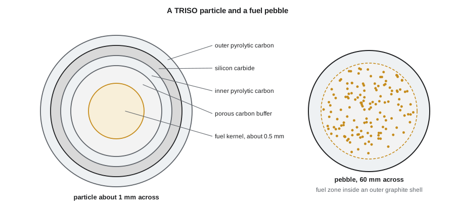
Tests have shown that TRISO particles retain their fission products to temperatures of about 1 600 °C for long periods, with failure rates rising above about 1 700 to 1 800 °C. The design approach for modular HTGRs is to keep fuel temperature below about 1 600 °C in every credible accident, including a complete loss of helium flow and pressure, by limiting the core power density and making the core tall and slender so that decay heat can conduct and radiate to the vessel wall and then to a passive cooling system outside the vessel. In this approach, the fuel particles, rather than a pressure-retaining containment, provide the main barrier to release.
Pebble bed and prismatic cores
In a pebble-bed reactor, hundreds of thousands of fuel pebbles fill a cylindrical cavity in a graphite reflector. Pebbles are added at the top and removed at the bottom while the reactor runs, measured for burnup, and either returned to the top for another pass or discharged. This gives on-power refuelling, a little like CANDU, and a low excess reactivity. In a prismatic-block reactor, fuel compacts sit in hexagonal graphite blocks stacked to form the core, with coolant channels through the blocks, and the reactor is refuelled in batches. The Xe-100 and the HTR-PM are pebble-bed designs; the earlier US Fort St. Vrain plant and several current designs are prismatic.
The helium loop
Helium enters the core at about 250 to 300 °C and leaves at about 700 to 750 °C in current steam-cycle designs. Because helium has a low density and modest heat capacity per unit volume, it must be pressurized to several megapascals and moved at high velocity. Circulators, large electric-driven blowers, keep it moving. The hot helium passes to a steam generator, which produces superheated steam at about 540 to 565 °C, as in a modern fossil plant, giving a net efficiency of about 40 percent. Future designs with even higher outlet temperatures could use a direct helium gas turbine cycle or supply hydrogen production.
# HTGR helium loop and TRISO fuel temperature margin (illustrative).
Q = 200e6                      # W thermal, one pebble-bed module
cp_he = 5193.0                 # J/(kg K)
T_in, T_out = 260.0, 750.0
m = Q / (cp_he * (T_out - T_in))
print(f"helium flow {m:5.1f} kg/s for a {T_out-T_in:3.0f} K rise")
# Blower power: pressure drop across the core and loop
dp, rho = 100e3, 3.8           # Pa, kg/m3 helium near 6 MPa and 500 C
P_blow = m * dp / rho / 0.8
print(f"circulator power about {P_blow/1e6:4.1f} MW, {P_blow/Q:4.1%} of thermal power")
# Fuel temperature in a pebble: surface to centre with uniform heat generation
q_peb = 1.0e3                  # W per pebble
r = 0.025; k = 15.0            # m, W/(m K) effective
dT = q_peb / (8 * 3.14159 * k * r) * 2   # sphere centre rise, rough
for T_surf in (650.0, 900.0, 1200.0):
    Tc = T_surf + dT
    margin = 1600.0 - Tc
print(f"surface {T_surf:6.0f} C: centre about {Tc:6.0f} C, margin to 1600 C {margin:5.0f} K")helium flow 78.6 kg/s for a 490 K rise circulator power about 2.6 MW, 1.3% of thermal power surface 650 C: centre about 862 C, margin to 1600 C 738 K surface 900 C: centre about 1112 C, margin to 1600 C 488 K surface 1200 C: centre about 1412 C, margin to 1600 C 188 K
The large temperature rise across the core keeps the helium flow moderate, and the circulator takes only one or two percent of thermal power. The pebble calculation shows how the margin to the fuel temperature limit shrinks as the coolant temperature rises; real designs check this with detailed codes for normal operation and for loss-of-cooling events, where pebble power falls to decay heat levels but the coolant is no longer removing heat.
Worked problem
Helium flow for a 200 MW module
A 200 MW thermal core heats helium from 260 to 750 °C. With c_p = 5 193 J/kg·K, what is the mass flow?
Show solution
- Temperature rise: 750 − 260 = 490 K.
- ṁ = 2.0 × 10⁸/(5 193 × 490) ≈ 78.6 kg/s.
- At about 6 MPa and 500 °C helium density is only a few kilograms per cubic metre, so the volume flow is around 20 m³/s.
Answer: About 79 kg/s of helium carries the full power, as the program shows; the large temperature rise is what keeps this manageable.
Safety characteristics
Modular HTGRs have several inherent safety features. Graphite has a very large heat capacity, so the core heats slowly if cooling is lost. The strongly negative fuel temperature coefficient shuts the chain reaction down as the fuel heats, even without control rods. Helium does not boil or react with fuel or graphite. A loss of forced cooling or even a depressurization of the primary system leads to a slow heat-up, over a day or more, to a peak fuel temperature below the limit, with heat removed through the reactor vessel to a reactor cavity cooling system that works by natural convection of air or water. The main accident challenges are air or water ingress into the hot graphite core, which can cause oxidation, and they are addressed in the design of the vessel and the steam generator.
Canada has examined HTGRs for oil sands and remote heat applications, and several designs have taken part in the CNSC's pre-licensing vendor design review. Ontario and Alberta universities have research programs on TRISO fuel and graphite.
Challenges
HTGRs have a larger core and vessel for a given power than water reactors because of their low power density. Graphite changes dimension and properties under irradiation, as NUC-340 described, and spent graphite and pebbles create a larger volume of waste per unit energy than LWR fuel. Helium leaks easily and must be managed. TRISO fuel needs high-assay low-enriched uranium in most current designs and specialized fabrication facilities. The economics depend heavily on whether high-temperature process heat is valued by the customer, which is why industrial sites are prominent among proposed deployments.
Graphite in the core
Graphite plays several roles in an HTGR: moderator, reflector, structural support and heat conductor. Nuclear graphite is made from petroleum or pitch coke, formed, baked and graphitized at about 2 800 °C, and purified to remove neutron absorbers such as boron. Under neutron irradiation, graphite first shrinks and later swells, and its strength, stiffness and thermal conductivity change. Reflector blocks near the core receive the highest dose and may need replacement during the life of the plant, depending on the design. Graphite in pebble-bed reactors also wears as pebbles move, producing fine graphite dust that carries some radioactivity and must be filtered from the helium.
Power conversion and process heat
Most near-term HTGRs use a steam cycle: the helium heats a steam generator that produces superheated steam, which drives a turbine or is supplied directly to an industrial user. A plant can split its output between electricity and process steam. For higher outlet temperatures, around 850 to 950 °C, an intermediate heat exchanger can transfer heat to a secondary helium loop or a molten salt loop that serves a chemical plant or a hydrogen production process, keeping the reactor's primary helium separate from the industrial process. A direct Brayton cycle, with the primary helium expanding through a gas turbine, has been studied for very high efficiency but adds challenges in turbine maintenance and fission product deposition.
Fuel cycle and spent fuel
HTGR fuel reaches high burnup per unit of heavy metal, but the fuel elements contain much more graphite than LWR fuel contains zirconium and steel, so the volume of spent fuel per unit energy is larger. The TRISO coatings that retain fission products in the reactor are also robust in long-term storage and disposal. Spent pebbles are typically stored in dry casks. The fuel supply chain for TRISO, from enrichment of HALEU to particle coating and pebble or compact fabrication, is being built up in the United States and elsewhere.
Comparing HTGRs with water reactors
Compared with a light water reactor of the same power, an HTGR has a larger core and vessel, a lower power density, a much higher outlet temperature, a coolant that cannot boil or flash, and a fuel that retains fission products at far higher temperatures. Its safety case relies more on inherent characteristics than on active systems, and its containment can be simpler. Its challenges are cost per kilowatt for a large, low-power-density core, graphite management, and the fuel supply chain. Which characteristics matter most depends on whether the customer needs electricity alone or high-temperature heat.
Instrumentation and control in a gas reactor
Measuring conditions inside an HTGR core is harder than in a water reactor. Core outlet temperatures are high, and pebble-bed cores have no fixed positions where detectors can sit among the fuel. Neutron flux is measured by detectors in the reflector or outside the vessel. Helium temperatures are measured at the core inlet and outlet plenums, and the operators infer fuel temperatures from these measurements combined with calculations. Melt-wire experiments in the AVR, where small samples of metals with known melting points were passed through the core inside pebbles, showed that some local temperatures were higher than predicted, a lesson that has shaped how designers set margins for current reactors. Control rods move in channels in the side reflector rather than in the core itself, and a separate reserve shutdown system, which drops small absorber spheres into channels in the reflector, provides a diverse means of shutdown.
Helium purification is another supporting system. A side stream of primary helium passes through filters, oxidizers and adsorbers that remove dust, moisture, tritium and chemical impurities such as carbon monoxide and hydrogen, which would otherwise corrode the graphite and metal components over time.
Common mistakes
MistakeHTGRs rely on a large containment like a PWR.
InsteadThey rely mainly on TRISO particles retaining fission products, with a vented reactor building in many designs.
MistakeHelium becomes highly radioactive in the core.
InsteadHelium itself barely activates; small amounts of impurities and dust carry the activity.
MistakePebble-bed cores must shut down to refuel.
InsteadPebbles are added and removed continuously at power.
Summary and key terms
- HTGRs use helium coolant, graphite moderator and TRISO fuel to reach outlet temperatures near 750 °C or more.
- TRISO particles retain fission products up to about 1 600 °C.
- Pebble-bed and prismatic cores are the two main configurations.
- Passive decay heat removal by conduction and radiation keeps fuel below its limit in accidents.
- High temperature makes HTGRs attractive for industrial process heat.
- TRISO particle
- A fuel kernel coated with carbon and silicon carbide layers that retain fission products.
- Pebble bed
- A core of spherical fuel pebbles that move through the reactor during operation.
- Prismatic core
- A core of hexagonal graphite blocks holding fuel compacts.
- Circulator
- A blower that moves helium through an HTGR primary circuit.
- Reactor cavity cooling system
- A passive system that removes heat from the outside of an HTGR vessel.
- Process heat
- High-temperature heat supplied directly to industrial processes rather than converted to electricity.
Practice problems
Work each problem on paper first, then reveal the answer to check.
What is the main fission product barrier in an HTGR?
Show answer
The silicon carbide and carbon coatings of the TRISO particles.
Why are HTGR cores tall and slender with low power density?
Show answer
So that decay heat can escape by conduction and radiation without exceeding the fuel limit.
What is the approximate fuel temperature limit for TRISO in accidents?
Show answer
About 1 600 °C.
Why can HTGRs reach about 40 percent efficiency?
Show answer
Their high outlet temperature produces superheated steam like a modern fossil plant.
Which Chinese plant was the first commercial modular HTGR?
Show answer
HTR-PM at Shidaowan.
Lesson quiz · 5 questions
Score 60% or more to complete this lesson.
Create a free account to save your progress, take quizzes and earn a certificate.