
NUC-360 · Lesson 11 of 12 · 20 min
Molten salt reactors
Hana has never seen a reactor whose fuel is a liquid. Dr. Teodora Vasquez pulls out a photograph from the 1960s: the Molten-Salt Reactor Experiment at Oak Ridge, a small reactor whose uranium was dissolved in a hot fluoride salt that flowed through a graphite core. "It ran for four years," she says. "Now Terrestrial Energy has taken its IMSR design through the CNSC's vendor design review, and the client wants to know whether liquid fuel is an engineering curiosity or a real option."
Two kinds of molten salt reactor
Molten salts are mixtures of fluoride or chloride compounds that are solid at room temperature and melt at a few hundred degrees Celsius. When molten, they are clear, stable liquids with high heat capacity per unit volume, low vapour pressure and boiling points far above any operating temperature. A reactor can use molten salt in two ways. In a fuel-salt reactor, the uranium is dissolved in the salt, and the salt is both fuel and coolant: it flows through the core, where fission heats it, then to a heat exchanger outside the core. In a salt-cooled reactor, the fuel is solid, usually TRISO particles in pebbles or compacts as in lesson 9, and clean molten salt cools it. Both are often called molten salt reactors; the second type is also called a fluoride salt-cooled high-temperature reactor.
Salt reactors operate at around 600 to 700 °C at near-atmospheric pressure, like sodium reactors, and with high-temperature heat useful for efficient power cycles and industry. Unlike sodium, molten fluoride salts do not burn in air or react violently with water. Their main challenges are corrosion of structural metals at high temperature, the high melting point of the salt, and, for fuel-salt designs, the chemistry and handling of a fuel that contains dissolved fission products.
The Oak Ridge experiments
Oak Ridge National Laboratory developed molten salt technology from the 1950s, first for a nuclear aircraft engine program and then for civilian power. The Molten-Salt Reactor Experiment ran from 1965 to 1969 at about 7.4 MW thermal, using a lithium-beryllium fluoride salt with dissolved uranium tetrafluoride flowing through a graphite moderator. It demonstrated stable operation, on-line addition of fuel, and the drain tank concept, and its records remain a key reference for designers today. Development stopped in the 1970s as the United States concentrated on sodium fast reactors, and interest revived in the 2000s.
Heat transport and the fuel salt loop
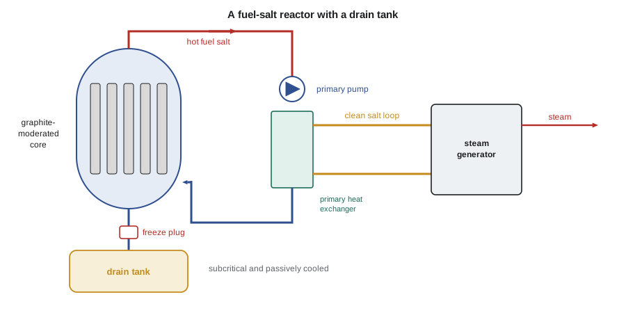
In a fuel-salt reactor, the whole primary loop carries fuel. The salt is heated in the core, typically by 50 to 100 K, and passes through pumps and heat exchangers outside the core. A secondary loop of clean salt then carries heat to a steam generator or another power cycle, isolating the steam system from the radioactive primary salt, just as the intermediate sodium loop does in lesson 10. The mass flow follows the same balance as in other reactors. Because the salt has a high volumetric heat capacity, the volume flow is modest:
The salt must stay well above its freezing point everywhere in the loop, so heat exchangers are designed to prevent cold spots, and electrical heating keeps pipes and vessels hot when the reactor is shut down. A freeze plug, a section of pipe cooled so that a plug of solid salt forms, can serve as a passive drain valve: if power to its cooling is lost or the salt overheats, the plug melts and the fuel salt drains by gravity into a drain tank designed to keep it subcritical and to cool it passively.
# Molten salt reactor: fuel salt loop heat transport and delayed neutron loss (illustrative).
Q = 400e6                       # W thermal
cp, rho = 1900.0, 2000.0        # J/(kg K), kg/m3 fluoride salt (rough)
T_in, T_out = 620.0, 700.0
m = Q / (cp * (T_out - T_in))
print(f"salt flow {m:5.0f} kg/s = {m/rho:4.2f} m3/s for an {T_out-T_in:2.0f} K rise")
# Margin to freezing: many fluoride salts freeze around 450 to 500 C
print(f"margin from inlet to a 460 C freezing point: {T_in - 460:4.0f} K")
# Delayed neutron precursors decay partly outside the core when the fuel circulates
beta = 0.0065
for t_core, t_loop in ((8.0, 0.0), (8.0, 8.0), (8.0, 16.0)):
    frac = t_core / (t_core + t_loop) if t_loop else 1.0
print(f"core {t_core:4.1f} s, external loop {t_loop:4.1f} s: rough effective beta {beta*frac:.4f}")salt flow 2632 kg/s = 1.32 m3/s for an 80 K rise margin from inlet to a 460 C freezing point: 160 K core 8.0 s, external loop 0.0 s: rough effective beta 0.0065 core 8.0 s, external loop 8.0 s: rough effective beta 0.0032 core 8.0 s, external loop 16.0 s: rough effective beta 0.0022
Delayed neutrons in a flowing fuel
One physics feature of liquid fuel is that delayed neutron precursors, the fission products that emit delayed neutrons seconds after fission, are carried around the loop with the salt. Some of them decay outside the core, where their neutrons cannot contribute to the chain reaction. The effective delayed neutron fraction is therefore lower than in solid fuel, and it changes if the pumps stop and the salt stops circulating. Since the delayed neutron fraction sets the margin between delayed and prompt criticality, as NUC-300 described, designers must account for this in control and safety analysis. The program's rough estimate, which simply scales by the fraction of loop time spent in the core, shows the size of the effect; detailed calculations account for each precursor group's half-life.
Worked problem
Effective delayed neutron fraction
Fuel salt spends 8 s in the core and 8 s in the external loop. Using the rough rule that delayed neutrons count only in proportion to the time spent in the core, estimate the effective delayed neutron fraction for β = 0.0065.
Show solution
- Fraction of loop time in the core: 8/(8 + 8) = 0.5.
- β_eff ≈ 0.0065 × 0.5 ≈ 0.0032.
- Longer-lived precursor groups are less affected in reality, so the true reduction is somewhat smaller.
Answer: Circulating fuel can roughly halve the effective delayed neutron fraction, which matters for reactivity control.
Materials and chemistry
Hot fluoride salts dissolve the protective oxide films that normally protect metals, so structural alloys must resist corrosion by other means. Oak Ridge developed a nickel-molybdenum alloy, Hastelloy N, for the MSRE. Corrosion depends strongly on salt purity and on its redox state, which designers control by keeping the salt slightly reducing. Tellurium from fission caused shallow grain-boundary cracking in the MSRE's alloy, and later work addressed this. Graphite in contact with salt must resist salt penetration and irradiation damage. Some fuel-salt designs, including the IMSR, avoid long-term exposure of components by replacing the whole reactor core unit after several years.
Fuel-salt reactors also release gaseous fission products, such as xenon and krypton, into the cover gas, where they can be removed and held for decay. Removing xenon-135 improves neutron economy. Some designs propose on-line chemical processing of the salt, but most near-term designs simply operate on a once-through basis and store the used salt.
Terrestrial Energy's Integral Molten Salt Reactor, or IMSR, a fuel-salt design with a sealed core unit replaced every seven years, completed phase 2 of the CNSC's pre-licensing vendor design review. Moltex Energy has developed a stable salt reactor concept with fuel salt in tubes, with work in New Brunswick.
Safety features and open questions
Molten salt reactors share the low-pressure advantage of sodium reactors without sodium's reactivity with air and water. The salt retains many fission products, such as caesium and strontium, chemically. Fuel-salt designs have a strongly negative temperature coefficient from salt expansion, which pushes fuel out of the core as it heats, and the drain tank provides a passive way to separate the fuel from the moderator. Open questions include long-term materials performance, the regulatory treatment of a liquid fuel and its off-gas system, tritium production in lithium- and beryllium-bearing salts, salt supply and enrichment of lithium-7, and the handling of used salt.
Choice of salt
Molten salt reactor designers choose salts for neutron behaviour, melting point, chemical stability and compatibility with materials. Fluoride salts such as FLiBe, a mixture of lithium fluoride and beryllium fluoride, have low neutron absorption if the lithium is enriched in lithium-7, a moderate melting point around 460 °C, and good chemical stability. FLiBe is used as the coolant in Kairos Power's designs and was the base salt of the MSRE. Sodium-based fluoride mixtures avoid beryllium's toxicity and lithium enrichment but absorb more neutrons. Chloride salts, used in some fast-spectrum fuel-salt designs, dissolve more uranium and plutonium and allow a fast spectrum, but chlorine-35 absorbs neutrons and produces long-lived chlorine-36, so enrichment in chlorine-37 may be needed.
Off-gas and cover gas systems
In a fuel-salt reactor, noble gases and some volatile fission products leave the salt and collect in the gas space above it. An off-gas system removes this gas, holds it in charcoal beds or tanks while short-lived isotopes decay, and filters it before any release. The off-gas system becomes a significant part of the radioactive inventory and of the safety analysis, because it holds activity outside the core. Salt-cooled reactors with solid fuel, by contrast, have a clean coolant in normal operation, and their cover gas carries much less activity.
Heat exchangers and power conversion
Primary heat exchangers in molten salt reactors must be compact, to limit the fuel salt inventory outside the core, and designed to avoid local freezing. The secondary loop usually uses a clean fluoride or nitrate salt, which in turn heats a steam generator producing superheated steam at about 540 °C for a turbine with efficiency near 45 percent, or supplies process heat. Some designs consider supercritical carbon dioxide Brayton cycles. Tritium produced in lithium- and beryllium-bearing salts can diffuse through hot metal heat exchanger walls, so tritium capture and permeation barriers are part of the design.
Licensing a liquid-fuelled reactor
Regulatory frameworks were written for solid fuel, where fuel damage limits such as cladding temperature define much of the safety case. For liquid fuel, the barriers are different: the salt itself, the primary loop boundary, the off-gas system and the containment structure. Regulators and developers have worked on how to define fuel and barrier performance criteria for these designs. The CNSC's vendor design reviews and the NRC's work on advanced reactor licensing have both addressed liquid-fuelled reactors.
Maintenance and remote handling
In a fuel-salt reactor, every component touched by the primary salt becomes highly radioactive and contaminated with fission products, so it cannot be maintained by hand after the reactor has operated. The MSRE relied on remote maintenance tools, operated from above the reactor cell through shielding, to replace components. Current designs address this in different ways. Some, like the IMSR, plan to replace the whole sealed reactor unit, including the pumps and primary heat exchangers, on a fixed schedule rather than repair components in place. Others design for remote replacement of pumps and heat exchangers. Salt-cooled designs with solid fuel have a less radioactive primary salt, which simplifies maintenance, though some activation products and tritium still require care. In every case, the plant layout must provide shielded cells, lifting paths and storage for used components, which shapes the size and cost of the reactor building.
Draining the salt for maintenance, and refilling and reheating the loop afterward, are also planned operations, because the salt must never be allowed to freeze in an uncontrolled way inside pumps or heat exchanger tubes.
Hana adds a row to her comparison table for each type of salt reactor. The salt-cooled designs, with solid TRISO fuel, inherit much of the HTGR fuel qualification work and have a clean coolant, so they appear closer to deployment. The fuel-salt designs promise higher fuel utilization and simpler fuel fabrication, but their licensing, maintenance and used-salt management are less developed. Malik agrees and asks her to note that both share the same materials question: how long structural alloys and graphite last in contact with hot fluoride salt.
Common mistakes
MistakeAll molten salt reactors dissolve the fuel in the salt.
InsteadSalt-cooled designs such as Kairos use solid TRISO fuel and clean salt coolant.
MistakeMolten fluoride salts burn in air like sodium.
InsteadThey do not burn and do not react violently with water.
MistakeDelayed neutrons are unaffected by circulating fuel.
InsteadSome precursors decay outside the core, lowering the effective delayed neutron fraction.
Summary and key terms
- Molten salt reactors use fluoride or chloride salts as coolant, and in fuel-salt designs as fuel.
- They operate at 600 to 700 °C at near-atmospheric pressure.
- The MSRE at Oak Ridge ran from 1965 to 1969 and remains a key reference.
- Drain tanks and freeze plugs provide passive fuel drainage.
- Corrosion control, materials and delayed neutron loss are key engineering issues.
- Fuel salt
- A molten salt with fuel dissolved in it, serving as both fuel and coolant.
- Fluoride salt-cooled high-temperature reactor
- A reactor with solid TRISO fuel cooled by clean molten fluoride salt.
- Freeze plug
- A plug of frozen salt in a drain line that melts to drain the fuel salt.
- Drain tank
- A tank below the core that holds drained fuel salt in a subcritical, passively cooled state.
- Hastelloy N
- A nickel-molybdenum alloy developed to resist fluoride salt corrosion.
- Redox control
- Keeping the salt chemically reducing to limit corrosion of structural metals.
Practice problems
Work each problem on paper first, then reveal the answer to check.
What is the difference between a fuel-salt and a salt-cooled reactor?
Show answer
Fuel-salt reactors dissolve the fuel in the salt; salt-cooled reactors use solid fuel with clean salt coolant.
Why do molten salt reactors run near atmospheric pressure?
Show answer
The salts boil far above operating temperature.
What does a freeze plug do?
Show answer
Melts to let fuel salt drain into a passively cooled drain tank.
Why is the effective delayed neutron fraction lower in a fuel-salt reactor?
Show answer
Some precursors decay outside the core.
Which alloy was developed for the MSRE?
Show answer
Hastelloy N.
Lesson quiz · 5 questions
Score 60% or more to complete this lesson.
Create a free account to save your progress, take quizzes and earn a certificate.