
NUC-360 · Lesson 6 of 12 · 20 min
Safety systems
Hana's next assignment is a design review of the emergency core cooling system for the second Darlington BWRX-300 unit. Dr. Rohan Desai gives her a single question to answer: "If every pump on the site stops and every diesel fails, where does the decay heat go, and for how long?" For the existing CANDU units the answer involves pumps, valves and operators. For the BWRX-300 the vendor says the answer is seven days without any power at all. Hana's job is to understand why.
The three fundamental safety functions
Every reactor safety system serves one of three functions: control reactivity, cool the fuel, and confine radioactive material. Reactivity is controlled by the shutdown systems that stop the chain reaction. Cooling must continue after shutdown, because fission products keep generating heat. Confinement is provided by the barriers described in lesson 1 and by the containment described in lesson 7. Safety systems are designed against a set of design basis events, ranging from frequent transients such as a turbine trip to rare accidents such as a large pipe break, and modern designs also consider beyond-design-basis and severe accidents.
Safety systems follow a few design principles. Redundancy provides more trains or channels than needed, so that one failure does not defeat the function. Independence and separation keep the trains apart physically and electrically, so that a fire or flood in one area cannot disable them all. Diversity uses different technologies for the same function, so that a common-cause failure of one design does not defeat the function. Fail-safe design makes the system move to its safe state when power or signals are lost, as when control rods drop if their magnets lose power. The single failure criterion requires the safety function to be achieved even with one active failure in addition to the initiating event.
Decay heat
After shutdown, the radioactive decay of fission products and actinides continues to produce heat. Immediately after a trip from long operation, decay heat is about 6 to 7 percent of the previous full power. It falls to about 1 percent after an hour and to a few tenths of a percent after a day, but it never stops quickly. For a large reactor, a few tenths of a percent is still several megawatts. The Way-Wigner approximation gives a rough estimate of decay heat as a fraction of operating power P₀, for a time t after shutdown following an operating period T:
Standards such as ANS-5.1 give more accurate decay heat curves for licensing calculations, but the simple formula captures the shape. The program below estimates decay heat at several times after a trip of a 3 411 MW reactor, the water flow it would boil away, and the total energy released over three days.
# Decay heat after shutdown and emergency coolant needed to boil it off (illustrative).
def decay_fraction(t, T=3.15e7):
    """Way-Wigner approximation: fraction of operating power t seconds after shutdown,
    after T seconds of operation (default one year). Rough, within tens of percent."""
    return 0.0622 * (t ** -0.2 - (t + T) ** -0.2)
P0 = 3411e6
h_boil = 2.26e6 + 4.18e3 * 70     # J/kg to heat water from 30 C and boil it
for label, t in (("1 s", 1), ("10 s", 10), ("1 min", 60), ("10 min", 600),
                 ("1 h", 3600), ("1 day", 86400), ("1 week", 604800)):
    f = decay_fraction(t)
    m = f * P0 / h_boil
    print(f"{label:>7}: decay heat {f:6.2%} = {f*P0/1e6:6.1f} MW, boils {m:6.1f} kg/s of water")
# Water needed to absorb decay heat for 72 hours without active pumps
E = 0.0
dt = 60.0
t = 60.0
while t < 72 * 3600:
    E += decay_fraction(t) * P0 * dt
    t += dt
print(f"energy from 1 min to 72 h: {E/1e12:5.2f} TJ, boiling about {E/h_boil/1000:6.0f} t of water") 1 s: decay heat 6.02% = 205.4 MW, boils 80.5 kg/s of water
10 s: decay heat 3.73% = 127.2 MW, boils 49.8 kg/s of water
1 min: decay heat 2.55% = 86.8 MW, boils 34.0 kg/s of water
10 min: decay heat 1.53% = 52.3 MW, boils 20.5 kg/s of water
1 h: decay heat 1.01% = 34.5 MW, boils 13.5 kg/s of water
1 day: decay heat 0.44% = 15.1 MW, boils 5.9 kg/s of water
1 week: decay heat 0.24% = 8.1 MW, boils 3.2 kg/s of water
energy from 1 min to 72 h: 3.94 TJ, boiling about 1543 t of waterAbout 1.5 thousand tonnes of water would be boiled away over three days. That is why passive designs carry very large water inventories, in pools above the reactor or in tanks inside containment, and why active designs need reliable pumps and power for days after an accident.
Shutdown systems
The reactor protection system monitors plant parameters such as neutron power, coolant pressure and temperature, flow, steam generator level and containment pressure. When any parameter crosses its trip setpoint, the protection system trips the reactor. In a PWR, control rods drop into the core within about two seconds; boron injection provides a diverse backup. In a BWR, hydraulic accumulators drive the control blades in from below, and a standby liquid control system can inject boron solution. CANDU has two fully independent shutdown systems, as lesson 4 described, each able to shut the reactor down on its own, with separate instrumentation and logic.
Emergency core cooling in active designs
If the reactor coolant pressure boundary breaks, the coolant is lost and the core must be refilled and cooled. Conventional large PWRs use several emergency core cooling subsystems. High-pressure injection pumps add borated water while the primary is still at high pressure, for small breaks. Accumulators, tanks of borated water pressurized with nitrogen, discharge passively into the cold legs when primary pressure falls below their pressure. Low-pressure injection pumps then supply large flows from the refuelling water storage tank. When that tank empties, the pumps switch to recirculation from the containment sump, drawing water that has collected on the containment floor, cooling it in heat exchangers and returning it to the core.
All of these pumps need electric power. Each unit has redundant emergency diesel generators that start automatically on loss of offsite power, and battery systems that keep instrumentation and controls running. Loss of all AC power, called station blackout, is a design consideration in its own right. Since the Fukushima Daiichi accident, plants have added portable pumps and generators, hardened connection points and offsite equipment centres that can deliver backup equipment within a day.
CANDU emergency core cooling has high-pressure, medium-pressure and low-pressure stages. In Darlington-type designs, high-pressure injection comes from water tanks pressurized by gas, medium-pressure injection is pumped from a large water supply, and long-term recovery pumps recirculate water collected in the reactor building, cooling it in heat exchangers. The moderator provides a backup heat sink for the fuel channels, and the shield tank provides another.
Passive safety systems
Passive safety systems use natural forces such as gravity, natural circulation, condensation and stored energy in compressed gas, rather than pumps and diesel generators. They usually still need valves to open, often by battery-powered or fail-open actuation, but once open they run without further power or operator action. The Westinghouse AP1000 uses a passive core cooling system with core makeup tanks, accumulators and an in-containment refuelling water tank that drains into the vessel by gravity after automatic depressurization, and a passive residual heat removal heat exchanger submerged in that tank. Its passive containment cooling system cools the steel containment shell by air flow and by water draining from a tank on the roof.
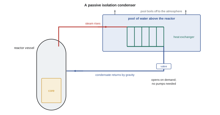
The BWRX-300 uses isolation condensers: heat exchangers submerged in large pools of water above the reactor. If the normal heat sink is lost, valves open and steam from the reactor vessel rises into the isolation condenser tubes, condenses, and the condensate drains back to the vessel by gravity. The decay heat boils the pool water, which is vented to the atmosphere. The pools hold enough water for about seven days without makeup. The BWRX-300 also relies on its integral isolation valves on the large pipes leaving the vessel, which are designed to close and stop a loss of coolant before it can uncover the core, so that the design does not need conventional emergency core cooling injection.
Worked problem
Pool inventory for seven days
Decay heat from 1 minute to 72 hours releases about 3.9 TJ for a 3 411 MW reactor. Scale to a 870 MW reactor and estimate the water boiled in three days, using 2.55 MJ/kg to heat and boil pool water.
Show solution
- Scale by power: 3.9 TJ × 870/3 411 ≈ 1.0 TJ.
- Water boiled: 1.0 × 10¹²/2.55 × 10⁶ ≈ 390 000 kg.
- About 390 m³ in three days; the boil-off rate keeps falling, so seven days needs well under twice that.
Answer: The isolation condenser pools need several hundred cubic metres of water above the reactor, which is consistent with the BWRX-300 design.
Instrumentation, procedures and operators
Safety systems need instruments to sense the plant state and logic to actuate equipment. Modern plants use digital protection systems with redundant channels and voting logic, often two-out-of-four, so that one failed channel neither trips the plant spuriously nor prevents a trip. Operators follow emergency operating procedures that are symptom-based: they respond to what the instruments show, such as low subcooling or high containment pressure, rather than trying first to diagnose the exact cause. Severe accident management guidelines extend the procedures to conditions beyond the design basis. Training on full-scope simulators, like the one Hana visited, is a licensing requirement for control room operators in both countries.
Defence in depth levels
International guidance describes defence in depth in five levels. Level 1 is prevention of abnormal operation through conservative design and high-quality construction and operation. Level 2 is control of abnormal operation and detection of failures, through control and limiting systems. Level 3 is control of design basis accidents by the safety systems described in this lesson. Level 4 is control of severe conditions, including prevention of accident progression and mitigation of severe accident consequences. Level 5 is mitigation of the radiological consequences of significant releases through offsite emergency response. Each level is meant to be as independent as practicable of the others, so that a failure at one level is caught by the next.
Probabilistic and deterministic analysis
Safety systems are analysed in two complementary ways. Deterministic safety analysis takes a defined list of initiating events, assumes conservative conditions and the worst single failure, and shows that the acceptance criteria, such as peak cladding temperature or fuel channel integrity, are met. Probabilistic safety assessment estimates the frequency of core damage and of large releases by combining the frequencies of initiating events with the probabilities that systems fail, using event trees and fault trees. Probabilistic results identify the sequences that matter most and guide improvements; modern designs aim for core damage frequencies well below one in a hundred thousand reactor-years, and many new designs claim values far lower. NUC-410 covers these methods in detail.
Spent fuel pool cooling
Safety systems also protect fuel outside the reactor. Spent fuel pools hold recently discharged fuel under several metres of water, which cools it and shields radiation. Pool cooling systems remove the decay heat, and makeup systems replace evaporation. After Fukushima, plants in both countries added pool level instruments that work in accident conditions and connections for portable makeup water, because a loss of pool cooling, while slow to develop, could eventually uncover the fuel.
Testing and surveillance
Safety systems spend almost their whole lives waiting, so plants must show regularly that they would work if called on. Technical specifications in the United States, and the operating policies and principles in Canada, set surveillance requirements: pumps are run and their flow and pressure checked, valves are stroked and timed, diesel generators are started and loaded, and instrument channels are calibrated and tested. Shutdown systems are tested at power by tripping one channel at a time, which the coincidence logic tolerates without shutting down the reactor. Components that cannot be tested at power are tested during outages. When a safety system is found inoperable, the specifications set a limited time to restore it, after which the reactor must be shut down. This combination of testing and allowed outage times is what makes the reliability assumptions in the safety analysis true in practice.
Common mistakes
MistakeDecay heat stops within minutes of a trip.
InsteadIt is about 6 to 7 percent of power at first and still several megawatts days later.
MistakePassive systems need no valves or signals at all.
InsteadThey usually need valves to open, but once open they run on natural forces.
MistakeThe single failure criterion means designs assume nothing fails.
InsteadIt requires the function to succeed with one failure in addition to the initiating event.
Summary and key terms
- Safety systems control reactivity, cool the fuel and confine radioactivity.
- Redundancy, independence, diversity and fail-safe design protect against failures.
- Decay heat is several percent of power at shutdown and falls slowly.
- Active emergency core cooling uses pumps and diesel generators; passive systems use gravity and natural circulation.
- The BWRX-300 uses isolation condensers and integral isolation valves to cope without power.
- Decay heat
- Heat produced by radioactive decay of fission products and actinides after shutdown.
- Single failure criterion
- A design rule requiring a safety function to succeed with one additional failure.
- Accumulator
- A tank of borated water pressurized with gas that injects passively when primary pressure falls.
- Station blackout
- Loss of all offsite and onsite AC power at a plant.
- Isolation condenser
- A heat exchanger in a pool that condenses reactor steam and returns it by gravity.
- Emergency operating procedure
- A symptom-based procedure that guides operators through abnormal events.
Practice problems
Work each problem on paper first, then reveal the answer to check.
What are the three fundamental safety functions?
Show answer
Control reactivity, cool the fuel and confine radioactive material.
About what fraction of full power is decay heat one hour after a trip?
Show answer
About 1 percent.
How does an accumulator inject without power?
Show answer
Its gas pressure pushes water into the primary when primary pressure falls below the tank pressure.
What does diversity protect against?
Show answer
Common-cause failures of one technology.
How long can the BWRX-300 isolation condenser pools remove decay heat without makeup?
Show answer
About seven days.
Lesson quiz · 5 questions
Score 60% or more to complete this lesson.
Create a free account to save your progress, take quizzes and earn a certificate.