
NUC-340 · Lesson 7 of 12 · 21 min
Creep and growth
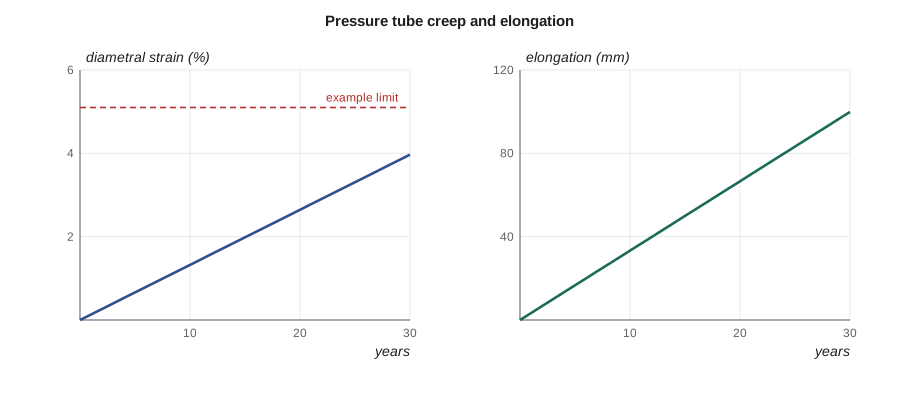
Malik shows Hana a plot that has guided CANDU life planning for decades: the measured diameter of pressure tubes against time in service, rising steadily from the day each unit started up. "At 300 degrees, zirconium would hardly creep at all without neutrons," he says. "In the core, under the pressure of the coolant, these tubes grow a few percent in diameter and tens of millimetres in length over their lives. When Darlington's original tubes were replaced, creep and growth were among the main reasons. The new tubes will follow the same curves, and we are already predicting where they will be in thirty years."
Thermal creep and irradiation creep
Creep is slow, permanent deformation under a constant stress. In most metals, thermal creep becomes significant above about 0.4 of the absolute melting temperature, so for zirconium (melting at about 2130 K) and for steels (about 1800 K) it is small at water reactor temperatures. Neutron irradiation changes this. The steady flow of vacancies and interstitials produced by irradiation allows dislocations to climb and glide even at low temperatures, and stress biases where the defects go. The result is irradiation creep: a creep rate roughly proportional to stress and to fast flux, and only weakly dependent on temperature.
where B is a creep compliance, φ the fast flux and σ the stress. Because the rate is proportional to flux, total irradiation creep strain is roughly proportional to fluence times stress. Thermal creep, which depends strongly on temperature and stress, adds to it in the hottest parts of components and during transients.
Irradiation growth
Irradiation growth is a change in shape at constant volume without any applied stress. It occurs in materials with anisotropic crystal structures, such as zirconium's hexagonal close-packed lattice. Interstitials and vacancies produced by irradiation do not go to the same places: interstitial loops tend to form on prism planes, which expands the crystal in the a-directions, while vacancy loops on basal planes, which appear at higher doses, shrink it along the c-axis. A single crystal therefore lengthens in the a-direction and shortens in the c-direction. In a textured tube, the net effect depends on the texture: most zirconium tubes are made with c-axes mainly in the radial and circumferential directions, so they grow in length.
| Effect | Driven by | Depends on | Typical consequence |
|---|---|---|---|
| Irradiation creep | flux and stress | stress, flux, texture, microstructure | pressure tube diameter growth; cladding creep-down onto pellets |
| Irradiation growth | flux, no stress needed | texture, cold work, dose; may accelerate at high dose | elongation of tubes and assemblies; bow |
| Thermal creep | temperature and stress | strongly on temperature | transients; dry storage; advanced reactors |
| Void swelling | flux at higher temperatures | temperature, helium, alloy | stainless internals near the core; fast reactors |
Growth in zirconium alloys can show breakaway: after a period of slow growth, the rate increases sharply when basal vacancy loops begin to form, typically at doses of several dpa. Recrystallised alloys and some niobium-bearing alloys resist breakaway better than cold-worked material. Fuel designs choose alloys and heat treatments with this in mind.
Pressure tube deformation in CANDU reactors
A CANDU pressure tube is a thin Zr–2.5 % Nb tube, about 6 m long, 103 mm inside diameter and about 4 mm thick, held at about 10 MPa and 250 to 310 °C in a high fast flux. It deforms in three ways at once.
| Deformation | Typical lifetime magnitude | Why it matters |
|---|---|---|
| Diametral creep | a few percent increase in diameter | coolant bypasses the fuel bundle, reducing critical channel power |
| Axial elongation | tens of millimetres to over 100 mm | the channels must slide in their bearings without running out of travel |
| Sag | tens of millimetres at mid-span | the pressure tube could approach its calandria tube; the tubes beneath it may also sag |
Diametral creep matters thermally as well as mechanically. As the diameter grows, more coolant flows around the outside of the bundle rather than through it, reducing heat removal from the hottest elements and lowering the critical channel power, an ageing effect included in the regional overpower trip setpoints, as NUC-330 discussed. Elongation is accommodated by bearings at each end that let the channel slide; operators periodically reposition channels to recover bearing travel. Sag is limited by garter springs and monitored so that the pressure tube never contacts its calandria tube, which would create a cold spot where hydride blisters could form, as in the 1983 Pickering event. These three effects together, with hydrogen pickup, set the life of a set of pressure tubes and were among the reasons for refurbishing the Darlington units.
Worked problem
When does diametral strain reach a limit?
A pressure tube operates at a fast flux of 3.5 × 10¹⁷ n/m²·s with a hoop stress of 130 MPa and a capacity factor of 90 percent. With a combined creep compliance and growth term giving a diametral strain of about 1.3 × 10⁻²⁸ per (n/m²), estimate the strain after 30 years and the time to reach an example limit of 5.1 percent.
Show solution
- Fluence per year = 3.5 × 10¹⁷ × 0.9 × 3.156 × 10⁷ ≈ 9.9 × 10²⁴ n/m².
- After 30 years the fluence is about 3.0 × 10²⁶ n/m², so the strain is about 3.0 × 10²⁶ × 1.33 × 10⁻²⁸ ≈ 4.0 percent.
- The 5.1 percent example limit is reached at about 0.051 / (1.33 × 10⁻²⁸ × 9.9 × 10²⁴) ≈ 39 years.
Answer: About 4 percent after 30 years and about 39 years to the example limit. Real predictions use measured creep rates for each tube, which vary with position along the channel, flux, temperature and microstructure.
# Creep and growth of a pressure tube: diametral strain and length change over time.
# Strain rate = (A * phi) * (stress term) + growth term; constants are illustrative.
phi = 3.5e17            # fast flux, n/m2/s
years = [0, 5, 10, 15, 20, 25, 30]
eff_full_power = 0.90 * 3.156e7   # seconds per year at 90 percent capacity
sigma_hoop = 130.0      # MPa, hoop stress at operating pressure
creep_coef = 1.1e-30    # strain per (n/m2) per MPa, irradiation creep compliance (illustrative)
growth_dia = -1.0e-29   # diametral growth per (n/m2), small and negative across the tube
growth_ax = 5.0e-29     # axial growth per (n/m2)
for y in years:
    fl = phi * eff_full_power * y
    dia = (creep_coef * sigma_hoop + growth_dia) * fl
    ax = (growth_ax + 0.05e-30 * 60.0) * fl
    print(f"{y:2d} years: fluence {fl:.2e} n/m2, diametral strain {100*dia:4.2f} %, axial elongation {ax*6.3*1000:5.0f} mm on a 6.3 m tube")
limit = 0.051            # an example licence-style limit on diametral strain
for y in range(0, 60):
    fl = phi * eff_full_power * y
    if (creep_coef * sigma_hoop + growth_dia) * fl > limit:
print(f"diametral strain reaches {100*limit:.1f} % after about {y} years"); break0 years: fluence 0.00e+00 n/m2, diametral strain 0.00 %, axial elongation 0 mm on a 6.3 m tube 5 years: fluence 4.97e+25 n/m2, diametral strain 0.66 %, axial elongation 17 mm on a 6.3 m tube 10 years: fluence 9.94e+25 n/m2, diametral strain 1.32 %, axial elongation 33 mm on a 6.3 m tube 15 years: fluence 1.49e+26 n/m2, diametral strain 1.98 %, axial elongation 50 mm on a 6.3 m tube 20 years: fluence 1.99e+26 n/m2, diametral strain 2.64 %, axial elongation 66 mm on a 6.3 m tube 25 years: fluence 2.49e+26 n/m2, diametral strain 3.31 %, axial elongation 83 mm on a 6.3 m tube 30 years: fluence 2.98e+26 n/m2, diametral strain 3.97 %, axial elongation 100 mm on a 6.3 m tube diametral strain reaches 5.1 % after about 39 years
Fuel cladding and assemblies
In light water reactor fuel, the cladding first creeps inward, because the coolant pressure exceeds the internal gas pressure, until it meets the swelling pellet. This creep-down closes the gap, which improves heat transfer but leads to pellet-cladding interaction during power increases. Later in life, as fission gas raises the internal pressure, the cladding may creep outward; licensing limits on rod internal pressure guard against outward creep large enough to reopen the gap. Rods also grow in length by irradiation growth, so each rod has an axial clearance in its assembly, and guide tubes and spacer grids grow too.
Fuel assembly bow occurs when growth and creep act unevenly across an assembly, for example because of flux gradients or hold-down forces. Severe bow can make control rods drag in their guide tubes or increase local power peaking where water gaps open between assemblies. Fuel vendors have addressed this with stiffer guide tubes and alloys with lower growth.
Swelling in stainless steels
At higher temperatures and doses, austenitic stainless steels can swell as vacancies cluster into voids. In water reactor internals, temperatures are mostly too low for large swelling, but in thick baffle plates near the core, where gamma heating raises the metal temperature, some swelling is possible over long lives, and it has been included in internals ageing evaluations. In sodium-cooled fast reactors, swelling of cladding and duct materials was a major problem in early programs, with volume increases of tens of percent in some steels. It led to cold-worked titanium-stabilised steels and to ferritic–martensitic steels, which swell much less, as Lesson 11 discusses.
Measuring deformation in service
Predictions of creep and growth are only as good as the measurements that calibrate them. In CANDU reactors, inspection tools driven through a defuelled channel measure the inside diameter at many points along the tube with ultrasonic or eddy current probes, map the wall thickness, locate garter springs, and measure the gap between the pressure tube and calandria tube. Channel elongation is measured at the end fittings during outages. Together these give, for each inspected channel, the actual creep strain and growth at each position, which are compared with predictions and used to update models.
For light water reactor fuel, assemblies are measured in the spent fuel pool after discharge. Length, bow, twist and grid width are recorded, and selected rods are examined in hot cells for diameter, oxide thickness and hydrogen. These data feed fuel performance codes and fuel design changes. Control rod drop times measured at every outage also give an indirect check that assemblies have not bowed enough to interfere with insertion.
| Measurement | Method | What it feeds |
|---|---|---|
| Pressure tube diameter and wall | ultrasonic and eddy current probes in a defuelled channel | creep models, critical channel power ageing, flaw evaluations |
| Pressure tube to calandria tube gap | eddy current and ultrasonic gauging | contact predictions, garter spring programs |
| Channel elongation | end fitting position measurements | bearing travel and repositioning plans |
| Fuel assembly length and bow | pool-side measurement stations | fuel design, core loading, control rod clearance |
| Rod diameter and oxide | hot cell examination | fuel performance code validation |
Creep in the long term
Creep remains a concern after fuel leaves the reactor. In dry storage, cladding temperatures of a few hundred degrees and the internal gas pressure of each rod give hoop stresses that could cause slow thermal creep over decades. Regulators and industry set limits on peak cladding temperature during drying and storage, commonly about 400 °C for normal conditions, partly to keep creep strains small and partly to avoid dissolving and then reorienting hydrides. These limits illustrate a general point: a material's history, in this case its irradiation, oxidation and hydrogen pickup in the core, decides how it behaves in its next stage of life.
For new designs operating at higher temperatures, thermal creep becomes the main design consideration rather than a secondary one. Lesson 11 shows how designers of high-temperature reactors use creep rupture data and time-dependent design rules, such as those in ASME Section III, Division 5, to choose materials for 60 years of operation above 500 °C.
Hana finishes the week by plotting the measured diameter of a set of inspected channels against the model. Most points sit close to the line, but a few channels near the core centre creep faster than predicted. Malik nods: that is exactly why every outage includes inspections, and why predictions are updated rather than trusted indefinitely.
Relaxation of bolts and springs
Irradiation creep has a quieter effect that matters just as much as diameter growth: relaxation. A bolt or spring that is preloaded and then held at a fixed displacement loses its preload over time as irradiation creep converts elastic strain into permanent strain. Baffle-former bolts in PWR internals, hold-down springs on fuel assemblies, and spacer springs in fuel bundles all relax this way. Designers allow for it by choosing higher initial preloads, materials with lower creep compliance, or designs that tolerate some loss of load. Inspections of internals bolts, and replacement where needed, are part of the ageing management programs for internals, because relaxed or cracked bolts can loosen baffle plates and let jets of coolant damage nearby fuel rods.
The equation shows the simplest model of relaxation under irradiation creep: stress decays exponentially with fluence, at a rate set by the elastic modulus E and the creep compliance B. Even a modest compliance can relax a large fraction of the initial preload over a few years in a high flux.
Summary and key terms
- Irradiation creep is roughly proportional to stress and fast flux, and weakly dependent on temperature.
- Irradiation growth changes shape at constant volume without stress, because of zirconium's anisotropic crystal structure.
- Texture controls the direction of growth; most zirconium tubes lengthen.
- CANDU pressure tubes creep in diameter, elongate and sag, which reduces critical channel power and must be accommodated and monitored.
- Light water reactor cladding creeps down onto the pellets, rods and assemblies grow, and assemblies can bow.
- Void swelling matters mainly at higher temperatures and doses, such as in fast reactors.
- Irradiation creep
- Creep that occurs because irradiation produces defects that let dislocations move.
- Irradiation growth
- Shape change at constant volume without stress, in anisotropic crystals.
- Creep compliance
- The constant relating irradiation creep rate to stress and flux.
- Breakaway growth
- A sudden increase in growth rate at higher dose, linked to basal vacancy loops.
- Sag
- Downward bending of a horizontal tube between its supports.
- Assembly bow
- Lateral bending of a fuel assembly from uneven growth and creep.
Practice problems
Work each problem on paper first, then reveal the answer to check.
Why is creep at 300 °C important in a reactor but not outside it?
Show answer
Irradiation produces defects that enable creep at temperatures where thermal creep is negligible.
What is the difference between irradiation creep and irradiation growth?
Show answer
Creep needs stress; growth happens without stress, at constant volume, because of anisotropy.
Why does diametral creep reduce critical channel power?
Show answer
More coolant bypasses the bundle through the larger annulus.
Name one consequence of fuel assembly bow.
Show answer
Slow or incomplete control rod insertion, or local power peaking at wider water gaps.
Which steels swell less in fast reactors?
Show answer
Ferritic–martensitic steels.
Lesson quiz · 5 questions
Score 60% or more to complete this lesson.
Create a free account to save your progress, take quizzes and earn a certificate.